
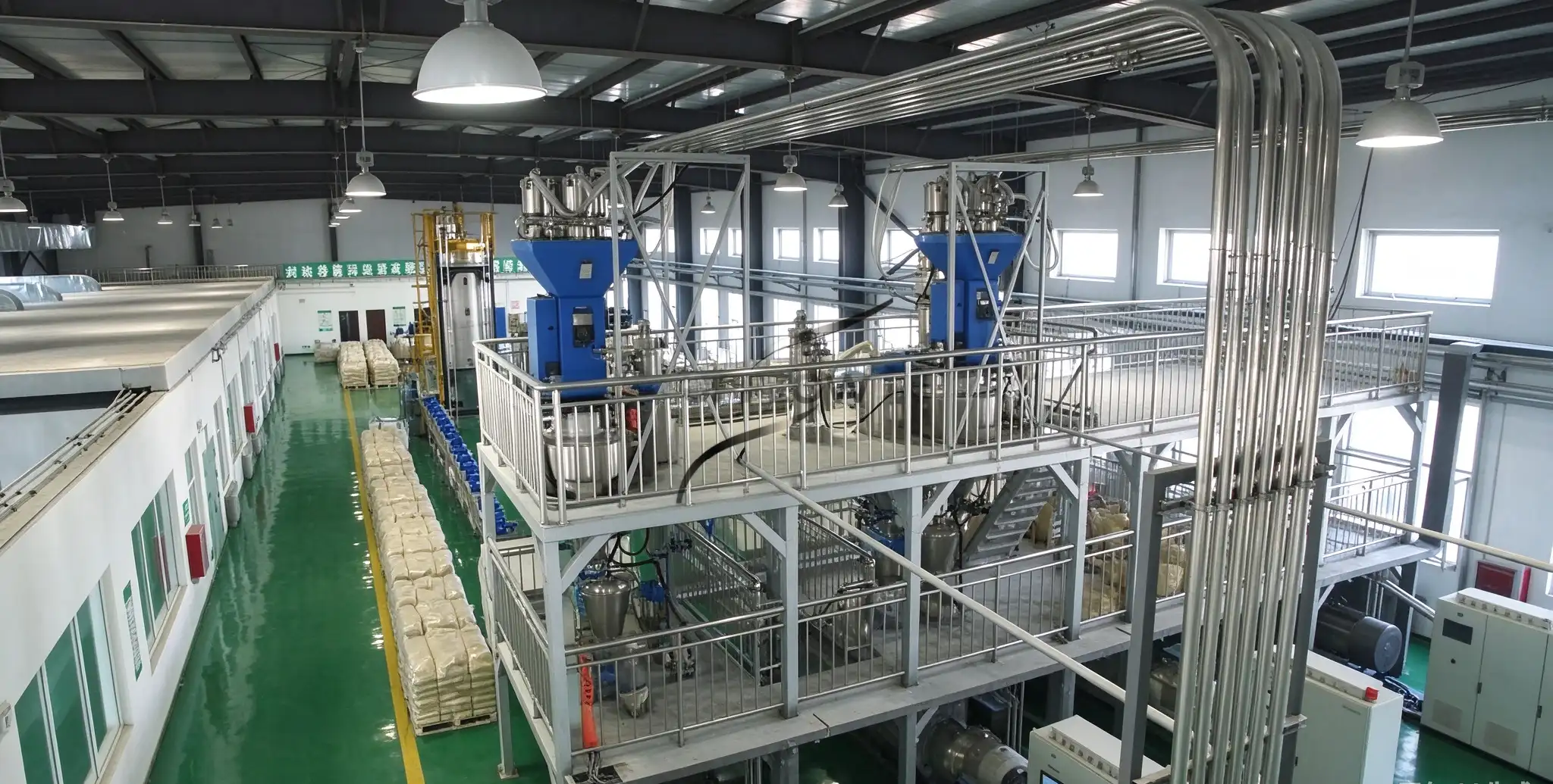
A powder batching hopper is an important component of an automatic weighing system. Its structural design, load cell installation and vibration control directly affect weighing stability and dosing consistency.
In industrial powder handling applications, even a high-quality load cell may produce unstable readings if the hopper has an unsuitable support structure, rigid pipeline connections or excessive mechanical vibration.
For chemical, food, pharmaceutical and battery material manufacturers, proper weighing hopper design should consider the vessel structure, material load, feeding equipment and downstream connections as an integrated system.
This article explains the key engineering considerations for designing a reliable powder batching hopper.
1. How to Select Load Cells for a Powder Batching Hopper
Load cells convert the mechanical force acting on a weighing hopper into electrical signals that can be processed by the weighing controller.
Their selection should consider the total supported load rather than only the maximum powder weight.
Important design inputs include:
Empty hopper weight.
Maximum material loading weight.
Number and position of load cells.
Load distribution and hopper center of gravity.
Operating environment and required accuracy.
For example, a hopper designed for 1,000 kg of powder must also support its own structural weight. Therefore, the total weighing load will be higher than the material weight alone.
Common industrial load cell types include compression load cells, shear beam load cells and tension load cells. The appropriate type depends on the hopper configuration and mounting arrangement.
It is also important to distinguish load cell accuracy from complete system accuracy. The final weighing performance depends on sensor installation, mechanical structure, controller configuration, material flow and operating conditions.
2. Load Cell Installation and Hopper Support Structure
A stable support structure ensures that the material load is transferred through the intended measuring direction.
Several engineering details should be considered:
Load distribution: Multiple load cells should be positioned according to the hopper geometry and expected center of gravity to avoid excessive uneven loading.
Mechanical rigidity: The support frame must withstand the maximum operating load without excessive deformation.
Side-load prevention: Suitable mounting assemblies should minimize unwanted horizontal forces and bending moments acting on the sensors.
Mechanical clearance: The hopper should not make unintended contact with nearby platforms, pipelines or support structures, as this may create alternative load paths and affect weight measurements.
The installation should also provide sufficient access for load cell inspection, replacement and maintenance.
3. How Vibration Affects Weighing Stability
Mechanical vibration can cause fluctuating weighing signals and make it difficult for the controller to identify the actual material weight.
Common vibration sources include:
Screw feeders connected to the weighing hopper.
Motors, mixers and rotating equipment.
Pneumatic conveying equipment.
Nearby production machinery.
Shared steel platforms and structural supports.
For example, a screw feeder mounted on the same structure as a weighing hopper may transmit vibration during material feeding.
Similarly, a rigid pipeline connection may transfer mechanical forces from upstream or downstream equipment into the weighing assembly.
The first step in solving unstable weighing signals is to identify the actual vibration source rather than immediately adding isolation components.
4. Vibration Isolation and Flexible Connections
Vibration isolation helps reduce unwanted mechanical transmission between the weighing hopper and surrounding equipment.
Depending on the installation, engineering solutions may include:
Dedicated support frames for weighing equipment.
Suitable elastomeric or spring vibration isolation components.
Flexible connections between the hopper and feeding equipment.
Flexible inlet and discharge connections.
Appropriate separation from nearby vibrating machinery.
Flexible connectors are particularly important when the hopper is integrated with screw feeders, pneumatic conveying pipelines or dust collection systems.
However, flexible connections must be selected according to material compatibility, pressure conditions, temperature and dust containment requirements.
The isolation arrangement must also maintain adequate structural stability. Excessive flexibility can introduce unwanted movement and increase weighing signal stabilization time.
The objective is to minimize external mechanical interference without compromising the safe support and accurate measurement of the hopper.
5. How to Verify Weighing Hopper Performance
After installation, the weighing arrangement should be checked under representative operating conditions.
A practical verification procedure includes:
Inspect the hopper support structure and load cell mounting.
Check mechanical clearances and flexible connections.
Verify zero stability and reference weight response.
Monitor weighing signals during screw feeder operation.
Observe signal stabilization after feeding stops.
Conduct repeated weighing tests and record actual batch results.
These checks help identify mechanical interference, unstable support conditions and feeding-related measurement disturbances.
For further guidance on dosing tolerances and verification methods, see our article on Powder Batching Accuracy: How to Define and Verify ±0.2% Tolerance.
6. Integrating Weighing Hoppers with Automatic Batching Systems
A weighing hopper should be designed as part of the complete powder handling process.
A typical automatic batching arrangement includes raw material storage, screw feeding equipment, load cell assemblies, weighing controllers, discharge valves and downstream mixing equipment.
Depending on the production requirements, the system may use sequential weighing, parallel weighing or a hybrid arrangement.
UPFLOW provides customized Automatic Batching Systems for multi-ingredient weighing and dosing applications.
For enclosed material transfer between storage and weighing equipment, a Pneumatic Conveying System or Vacuum Feeding System may also be considered according to the material characteristics and conveying requirements.
For additional engineering information, read Multi-Ingredient Powder Batching: Sequential vs Parallel Weighing.
7. UPFLOW Project References
European Artificial Graphite Airflow Mixing Project
UPFLOW has supplied 12 airflow mixing machines to a European battery material manufacturer through four separate contracts.
The project handles artificial graphite powder with a particle size below 20 μm and a bulk density of approximately 0.85 t/m³.
Each mixing machine has a 60 m³ design volume and a maximum loading weight of 30 tonnes per batch. The technical requirements also include a mixing cycle of no more than 30 minutes, CV ≤5% mixing uniformity and C3-class weighing load cells or better.
This project demonstrates the importance of integrating weighing equipment, material feeding, large-capacity vessels and process control.
Read more about the European Artificial Graphite Airflow Mixing Project.
Magnesium Silicate Conveying and Batching Project
UPFLOW supplied a customized pneumatic conveying and batching system for an overseas industrial customer. The system integrated bag dumping, pneumatic conveying, weighing hoppers, screw feeding and centralized control.
Read more about the Magnesium Silicate Pneumatic Conveying and Batching Project.
PVC Powder Feeding and Conveying Project
UPFLOW also supplied a customized PVC powder feeding and vacuum conveying system incorporating bag unloading equipment, conveying units, receiving hopper modifications, stainless steel pipelines and centralized electrical control.
This project demonstrates the importance of coordinating material receiving equipment, hopper structures and downstream production interfaces.
Read more about the PVC Powder Feeding and Vacuum Conveying Project.
8. Frequently Asked Questions
Q1. Why does a powder weighing hopper need vibration isolation?
Vibration isolation can reduce unwanted mechanical forces from feeders, mixers and nearby machinery, helping improve weighing signal stability.
Q2. How many load cells are required for a weighing hopper?
The number depends on hopper geometry, total supported load, center of gravity and load distribution.
Q3. Can a screw feeder affect load cell readings?
Yes. Mechanical vibration and rigid connections may transmit forces into the weighing structure and affect measurement stability.
Q4. Does a high-accuracy load cell guarantee accurate batching?
No. Complete system performance also depends on mechanical installation, hopper structure, feeding behavior, weighing instruments and operating conditions.
Q5. Can flexible connections improve weighing stability?
They can help reduce mechanical force transmission between connected equipment, provided that they are correctly selected and installed.
Conclusion
Reliable powder batching hopper design requires coordination between the vessel structure, load cells, support arrangement, vibration isolation and material transfer connections.
Rather than selecting load cells based only on their nominal accuracy, manufacturers should evaluate the complete mechanical and weighing arrangement under actual operating conditions.
UPFLOW provides customized powder batching, weighing hopper and pneumatic conveying solutions according to material properties, batch capacity and production requirements.
Planning a powder batching project? Contact UPFLOW with your material details, target weighing capacity and equipment drawings to discuss a suitable engineering configuration.