
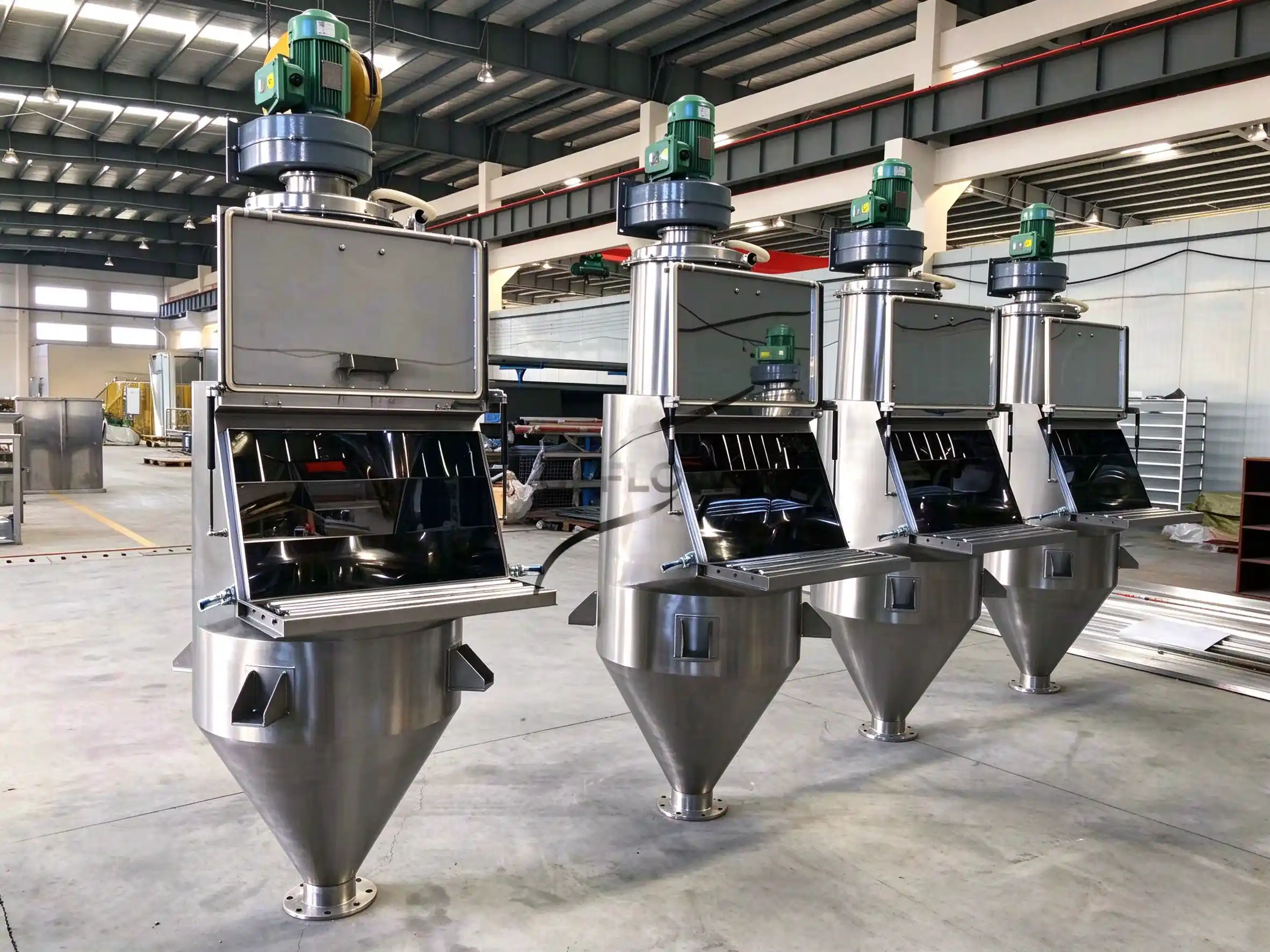
25 kg Bag Dump Station Design: Hopper Size, Work Height and Dust Capture
A 25 kg bag dump station should be designed around the operator’s handling task, the powder volume released during tipping, dust capture at the opening and the capacity of the downstream equipment. Bag mass alone cannot determine hopper size, working height or extraction airflow. Start with the actual bag, material and production sequence.
This 25 kg bag dump station design guide helps buyers define a manual sack tipping station for small-bag powder feeding. It focuses on hopper sizing, work height and dust capture, with a worked example whose assumptions are explicit. It does not treat an equipment photograph or a nominal bag weight as a verified production rating.
Define the operator’s complete task
Map the sequence from the incoming pallet to the receiving process: identify the bag, bring it to the station, support it, open it, tip the powder, manage the empty packaging and confirm the transfer. Include cleaning and recipe changes. The design must accommodate these activities without requiring the operator to reach around obstacles or shake an empty bag outside the capture area.
Record bag dimensions and construction, pallet position, expected operators and planned shift pattern. A 25 kg bag can be awkward because of its size, flexibility or grip even when its mass is familiar. Assess the actual handling task and consider a bag lifter, conveyor or other handling aid where appropriate.
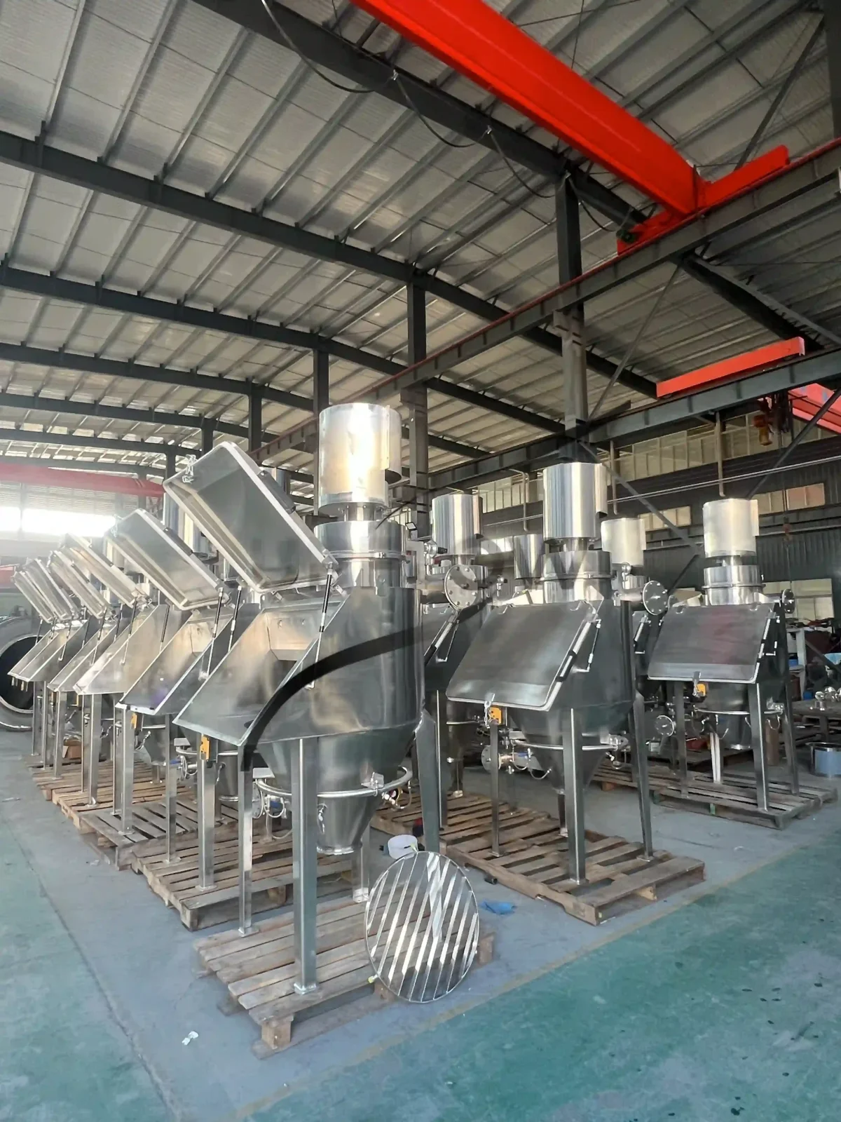
UPFLOW’s manual bag dump station description identifies dust collection, optional screening or magnetic separation and connections to vacuum or screw conveyors. Select the required configuration for the material and process rather than assuming every station includes each option.
Size the hopper from powder volume and timing
Convert bag mass into powder volume using representative bulk density. Specify whether the density is loose, settled or aerated and how it was measured. A powder disturbed during bag opening may occupy more space than a compacted sample, so a single catalogue density may not describe the tipping condition.
The initial relationship is volume = mass ÷ bulk density. Then assess how many bags can enter before the downstream equipment removes material. Account separately for the inlet zone, level controls, internal fittings and the space required to prevent overflow. Geometrical hopper volume is not automatically usable working volume.
Illustrative calculation with assumed conditions: assume a 25 kg bag and a loose bulk density of 500 kg/m³. One bag occupies approximately 0.05 m³, or 50 litres. If two bags are tipped while the outlet is unavailable, they add approximately 100 litres. A hypothetical 150-litre working allowance would leave 50 litres beyond that assumed powder volume; it is a starting point for review, not a universal hopper recommendation or tested UPFLOW specification.
Confirm that the assumed allowance covers the actual powder condition and operating sequence. For cohesive material, hopper angle and outlet size require a flow assessment; a larger vessel can still bridge. The support grille, optional screen and outlet arrangement must also be considered when assessing accessible capacity and retained material.
Compare the downstream feeding arrangements
| Arrangement | Design question | What to verify |
|---|---|---|
| Gravity discharge | Can the receiver accept the tipping surge? | Available receiving volume, venting and level response |
| Screw feeder | Does the feeder remove powder at the required rate? | Inlet geometry, refill behaviour, isolation and retained material |
| Batch vacuum transfer | What happens while the receiver discharges or cleans its filter? | Complete transfer cycle and station buffer requirement |
| Weighed batch addition | Where is the ingredient quantity measured? | Weighing boundary, stable measurement and recipe confirmation |
Compare the average bag input with the average powder removal rate. If the operator adds material faster than the line removes it, increasing hopper volume only delays the eventual high-level condition. Define a clear stop-to-feed indication and a restart condition instead of relying on the operator to estimate remaining space.
For process integration, see conveying and batching system interfaces. Decide whether bags are complete recipe ingredients or whether the process needs controlled partial dosing. A manually emptied bag does not by itself establish an accurate recipe quantity.
Choose working height using a real handling trial
A useful station height allows the intended operator to support, open and empty the actual bag without excessive bending, shoulder elevation or forward reach. Evaluate the full movement, including picking up the bag and removing the packaging. The height of the front shelf is only one dimension in that task.
Use a mock-up or adjustable trial arrangement before fixing the final drawing. Include the proposed bag lifter if one is planned. Check access for different operators, room for the feet, door movement, visibility of the hopper and the location of controls. Document the agreed arrangement rather than copying a height from another installation.
Place pallet replenishment and empty-bag collection so that they do not cross the operator’s working position. Confirm that maintenance access remains available after the station is connected to conveyors, ducts and platforms. A compact equipment footprint can still require substantial operating and service space.
Design dust capture around the opening
Contain the source as far as the task allows, then arrange extraction so that dust released during cutting and tipping moves into the capture area. Consider the open door, bag position, operator movement and nearby air currents. Air supplied by a fan, doorway or vehicle route can disturb the intended capture pattern.
Airflow cannot be selected from the 25 kg bag mass alone. The opening geometry, powder dustiness, release rate, duct losses and filter loading all matter. Specify the extraction duty with the equipment and ventilation designers, including the conditions under which it must be maintained.
For a simple airflow relationship, Q = v × A, where Q is volume flow, v is average velocity and A is the measurement area in consistent units. This relationship helps interpret measured airflow; it does not select an appropriate capture velocity or demonstrate containment. A validated design needs the actual geometry and task.
Check capture during bag opening, tipping and empty-bag handling. An apparently clean station at rest does not demonstrate capture during production. Use an agreed verification method and qualified personnel for exposure measurements where required. Material hazards, combustible dust characteristics and applicable site requirements need their own assessment.
Specify filters and empty-bag handling together
Decide whether extracted powder returns to the process or is collected separately. For recipe-controlled or allergen-sensitive production, returned dust can affect material accounting and changeover procedures. Choose filter materials and cleaning methods appropriate to the powder and the agreed hygiene requirements.
Make filters accessible for inspection and replacement without unnecessary powder release. Identify the isolation and cleaning procedure. Where filter differential pressure is monitored, define what the indication means and the response to an abnormal condition; a pressure reading alone does not prove that every seal and filter element is intact.
Keep empty packaging within the intended containment arrangement until residual powder is managed. A bag compactor or dedicated waste chute can change the space, access and extraction requirements. Include it in the original layout rather than treating waste bags as a separate housekeeping detail.
Verify the design with representative production
Test the actual material and bag format, with the downstream machine following its normal operating cycle. Record bag rate, operator actions, hopper level response, interruptions, residue and cleaning steps. Observe whether the operator needs to push material through the grille or shake bags in an unintended position.
Distinguish a short demonstration from sustainable shift output. Include replenishment, waste-bag handling and planned cleaning in the capacity review. Use a clear test boundary, so that a delay caused by the receiver is not incorrectly described as a limitation of manual tipping alone.
Send UPFLOW the powder data, required throughput, conveying distance and site conditions, together with bag dimensions and a layout, to discuss a station and downstream feeding arrangement. Browse the unpacking and feeding equipment range for the starting configuration.
Watch the equipment demonstration
The equipment demonstration shows manual sack tipping. Confirm the selected station, material and operating sequence for your own project.
Watch this UPFLOW equipment video on YouTube.
Frequently asked questions
How large should the hopper be for a 25 kg bag?
Calculate powder volume from representative bulk density, then check bag overlap, downstream availability and usable working space. There is no single hopper volume appropriate for every 25 kg powder bag.
Can one station feed a mixer and a vacuum conveyor?
It can be considered within a defined process arrangement. Specify routing, isolation, receiver availability and cleaning requirements. For larger-scale interfaces, compare the unloading and conveying system overview while retaining the manual station’s distinct handling requirements.
What information is needed to select the work height?
Provide the actual bag, pallet arrangement, operator task and any handling aid. Ask UPFLOW to review the material, throughput, distance and operating conditions alongside a handling trial before finalising the drawing.