
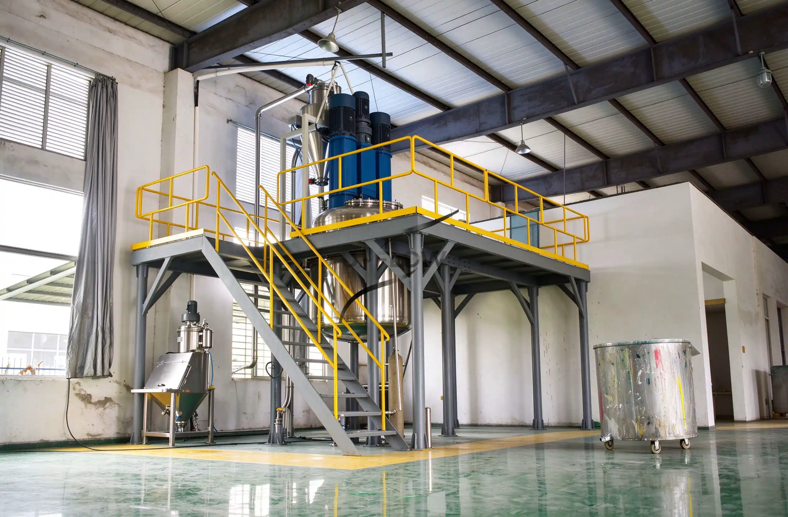
A properly designed dust collection system is an essential part of an industrial bag dump station, particularly when operators manually open and discharge fine powders from 25 kg bags or other small packaging into a receiving hopper. During bag cutting, tipping and empty packaging removal, airborne particles can escape from the feeding area, creating workplace contamination, material loss, cleaning requirements and potential operator exposure.
Selecting an appropriate dust collector requires more than choosing a fan with a high airflow rating or installing a filter with a fine filtration specification, because effective dust capture depends on the opening geometry, operator movements, powder release characteristics, enclosure design, duct resistance and filter operating conditions.
For manufacturers planning a new manual bag dumping station, the airflow and filtration system should therefore be designed together with the feeding hopper and downstream conveying equipment, ensuring that dust generated during material handling can be captured without unnecessarily disturbing the powder feeding process.
1. Why Does a Bag Dump Station Need a Dedicated Dust Collection System?
When operators open a powder bag and pour its contents into a receiving hopper, the falling material displaces air inside the hopper and can generate airborne dust, particularly when handling fine powders with low particle sizes or high dustiness.
The dust release may become more noticeable when operators shake empty bags, cut packaging, transfer powder from a considerable height or handle materials that generate significant airborne particles during impact.
A properly designed dust collection arrangement serves several purposes:
Captures airborne dust near the bag opening and material discharge point.
Maintains suitable negative pressure within the designated enclosure.
Reduces powder accumulation around the operator’s working area.
Helps maintain a cleaner material handling environment.
Supports integration with downstream powder feeding and conveying equipment.
Provides a controlled method for collecting and managing captured powder.
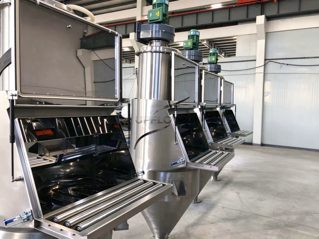
UPFLOW’s Manual Bag Dump Station is designed with an integrated dust collection arrangement, while the available configuration can also include screening and other auxiliary equipment according to the application.
However, the actual dust collector configuration and extraction airflow should be selected according to the material, feeding operation and required containment performance rather than assuming that one standard fan specification suits every powder.
2. What Determines the Required Airflow of a Bag Dump Station?
The required extraction airflow is primarily determined by the geometry of the dust-generating opening and the airflow needed to capture airborne particles before they escape into the surrounding working environment.
Several design factors should be evaluated during the initial engineering stage.
2.1 Bag Dump Station Opening Dimensions
The size and configuration of the feeding opening directly influence the airflow required to maintain suitable dust capture.
A fully enclosed feeding chamber with a relatively small operator access opening may require a different extraction arrangement from a large open tipping platform, because the effective air entry area and the locations where dust can escape are different.
When evaluating the opening, engineers should consider:
Width and height of the operator access opening.
Whether the feeding door remains open during bag tipping.
Position of the operator relative to the dust source.
Location of the dust extraction connection.
Whether the empty bag is handled inside or outside the enclosure.
Potential interference from nearby air currents or production equipment.
The objective is to create an airflow pattern that draws airborne particles toward the extraction point without allowing dust to escape through the operator access area.
2.2 Powder Characteristics
Different powders can generate very different dust loads during manual feeding, even when the same bag size and feeding station are used.
For example, fine mineral powders, starch, flour, chemical powders and battery material powders may differ in particle size distribution, moisture content, cohesion and airborne dust behavior.
The following material information should be collected before selecting the dust collector:
| Material parameter | Why it matters |
| Particle size distribution | Influences airborne particle behavior and filter selection |
| Bulk density | Helps define material volume and feeding conditions |
| Moisture content | May affect adhesion, agglomeration and filter cleaning |
| Dustiness | Influences the expected dust loading |
| Hygroscopic properties | May affect filter fouling and material handling |
| Combustible dust characteristics | May require additional process safety evaluation |
| Chemical properties | Determine suitable filter media and material compatibility |
A powder with high dust generation may require a more carefully designed enclosure and extraction arrangement than a less dusty granular material, even if both are processed through the same nominal bag dump station.
2.3 Bag Opening and Discharge Operation
Airflow requirements should be evaluated during the actual operating sequence rather than only when the bag dump station is empty.
The main dust-generating activities typically include opening the bag, pouring the powder, shaking out residual material and handling the empty packaging.
If the dust collector performs adequately during normal powder discharge but loses capture effectiveness when operators remove empty bags, the overall dust control arrangement may still be unsuitable.
For this reason, the extraction design should consider the complete operator workflow and the different positions of the access door throughout the feeding cycle.
3. How to Calculate the Required Dust Collection Airflow
A preliminary airflow calculation can help engineers understand the relationship between the opening area and the required air volume, but the selected design airflow must also account for the actual dust capture conditions and system resistance.
For a simplified opening-based calculation, the relationship is:
Q = V × A
Where:
Q = Required volumetric airflow (m³/s)
V = Average air velocity through the effective opening (m/s)
A = Effective open area (m²)
To convert the result into cubic meters per hour:
Q (m³/h) = V × A × 3,600
For example, if a hypothetical feeding station has an effective open area of 0.30 m² and the engineering team is evaluating an assumed average inward airflow velocity of 0.5 m/s, the preliminary airflow calculation would be:
Q = 0.30 × 0.5 × 3,600
Q = 540 m³/h
This is only an illustrative calculation, not a recommended design airflow for UPFLOW equipment or a universal capture velocity for manual bag dumping.
The actual required airflow should be determined through an assessment of the dust source, enclosure geometry, operator activities, nearby air disturbances and the applicable industrial ventilation requirements.
3.1 Why the Opening Area Is Not the Only Factor
The airflow calculated from the opening area does not automatically represent the final fan selection, because the dust collection system also includes ductwork, elbows, filter elements, valves and other components that create resistance.
For example, a system with a long extraction duct and several bends may require a different fan operating point from a system with a short, direct connection, even when both stations have the same nominal opening dimensions.
The design should therefore establish the required airflow at the operating point of the complete extraction system rather than selecting a fan using its free-air maximum airflow rating.
3.2 Consider Airflow During Actual Production
The airflow should remain suitable when operators are opening bags and discharging material, because the conditions during production may differ significantly from those during an idle equipment test.
Air entering through nearby doors, ventilation systems or other production equipment may disturb the intended capture pattern.
A practical verification should therefore examine dust containment during representative bag opening, tipping and empty-bag handling operations.
4. How to Select the Correct Filter Area
After determining the required airflow, the next step is to evaluate the filtration area needed to handle the expected dust loading while maintaining acceptable filter pressure drop and cleaning performance.
One important parameter used in dust collector design is the air-to-cloth ratio, also known as the filtration velocity.
It describes the relationship between the airflow passing through the filter and the effective filter media area.
The simplified calculation is:
Air-to-Cloth Ratio = Airflow / Effective Filter Area
Where:
Airflow is expressed in m³/min.
Filter area is expressed in m².
The resulting filtration velocity is expressed in m/min.
For example, if a dust collector operates at 10 m³/min and has an effective filter area of 20 m²:
10 ÷ 20 = 0.5 m/min
This is an illustrative calculation rather than a universal recommended filtration ratio, because the appropriate value depends on the dust characteristics, filter media, cleaning mechanism and operating conditions.
4.1 Factors Affecting Filter Area Selection
The required filter area should be evaluated according to:
Expected dust loading during bag dumping.
Particle size distribution and material characteristics.
Filter media permeability and surface properties.
Pulse cleaning frequency and effectiveness.
Acceptable differential pressure during operation.
Continuous or intermittent operating conditions.
Required filter service life and maintenance intervals.
A dust collector with insufficient filter area may experience excessive pressure drop and frequent cleaning, while an unnecessarily large filter arrangement may increase equipment dimensions and initial investment without providing a meaningful improvement in the actual dust capture performance.
4.2 Cartridge Filters vs. Bag Filters
Cartridge filters and bag filters are both used in industrial dust collection systems, but their suitability depends on the dust characteristics and equipment configuration.
| Comparison factor | Cartridge filter | Bag filter |
| Filter structure | Pleated filter media | Fabric filter elements |
| Filter area | Relatively high area in a compact arrangement | Depends on bag dimensions and quantity |
| Installation space | Often suitable for compact dust collectors | May require a larger filter housing |
| Cleaning method | Can use pulse-jet cleaning | Can use pulse-jet or other cleaning methods |
| Typical application | Fine dust collection and compact equipment | Industrial dust collection across various applications |
| Selection factors | Dust characteristics, media and pleat cleaning | Fabric compatibility, dust loading and cleaning conditions |
Neither filter type is automatically better for every powder application, because the selected media and cleaning arrangement must be compatible with the actual dust, moisture conditions, operating temperature and maintenance requirements.
5. How to Select Suitable Filter Media
Filter media selection is another important part of dust collector design, because the filtration material must be compatible with the powder and operating environment.
Common considerations include:
5.1 Polyester Filter Media
Polyester is widely used in industrial dust collection because it provides a practical filtration material for many general powder handling applications.
Its suitability depends on the operating temperature, chemical compatibility, moisture conditions and required filtration performance.
5.2 Anti-Static Filter Media
When handling powders with combustible dust characteristics or applications where static electricity requires control, anti-static filter media may be considered as part of the overall equipment design.
However, anti-static filter media alone does not make a dust collection system explosion-proof or eliminate ignition risks.
The dust hazard assessment, grounding and bonding, equipment design and applicable protection measures must be evaluated separately by qualified personnel.
5.3 PTFE-Coated and Other Specialized Media
Certain specialized filter media, including PTFE-coated materials, may be considered when powder adhesion, moisture conditions or cleaning requirements make conventional media unsuitable.
The choice should be based on actual process conditions rather than selecting a higher-cost filter material simply because it has a more advanced specification.
5.4 Why Filtration Precision Is Not the Only Selection Criterion
A filter specification expressed in microns does not independently establish the overall performance of a dust collection system.
The actual result also depends on filter media construction, sealing, air leakage, installation quality, cleaning performance and the operating conditions.
For buyers, it is therefore more useful to request the filter media specification, filtration area, design airflow, operating differential pressure and dust emission acceptance criteria together rather than comparing equipment only by a single micron rating.
6. Fan Selection, Duct Resistance and Filter Cleaning
The dust collection fan must be selected according to the required airflow at the system’s actual operating resistance.
The resistance of the system can include:
Airflow resistance at the feeding opening.
Duct friction and local resistance.
Elbows, reducers and connection fittings.
Filter media resistance.
Dust accumulation on the filter surface.
Discharge and cleaning components.
A fan that provides sufficient airflow under free-air conditions may not achieve the required operating airflow after the complete filter and ductwork system is connected.
6.1 Differential Pressure Monitoring
Differential pressure monitoring provides information about the pressure difference across the filter elements and can help operators identify changes in filter resistance.
An increasing differential pressure may indicate dust accumulation, insufficient cleaning, filter blockage or other operating issues.
The monitoring arrangement should establish suitable operating limits and maintenance procedures according to the selected dust collector.
6.2 Pulse-Jet Cleaning
Pulse-jet cleaning uses compressed air to periodically remove accumulated dust from the filter media.
The cleaning sequence and compressed air supply should be matched to the filter design, dust characteristics and operating conditions.
The system should also provide suitable access for inspecting and replacing filter elements without unnecessarily releasing collected powder into the working area.
6.3 Dust Discharge and Collection
The collected powder needs a defined discharge and handling arrangement.
Depending on the process, captured dust may be collected in a removable container or returned to the production process through a suitable discharge arrangement.
However, returning captured powder should only be considered when the material quality, contamination control, batch accounting and process requirements permit it.
For sensitive applications, the dust collection and disposal strategy should be confirmed with the customer before equipment fabrication.
7. Integration with Bag Dump Stations and Powder Conveying Systems
A dust collector should not be designed as an isolated component, because the feeding station, hopper, extraction duct and downstream material handling equipment operate as one integrated process.
A typical arrangement may include:
Manual Bag Dump Station → Receiving Hopper → Screw Feeder or Vacuum Feeder → Downstream Production Equipment
The dust collector is connected to the designated extraction point of the feeding station, maintaining the required air movement during bag opening and powder discharge.
For applications requiring automatic powder transfer, the manual bag dumping station can also be connected to a vacuum conveying system or another suitable conveying arrangement.
For example, UPFLOW’s Pneumatic Conveying System can be evaluated as part of an integrated powder handling process when materials need to be transferred from the bag dumping area to a remote silo, mixer or production machine.
Where the application requires weighing and controlled ingredient feeding, an Automated Batching System may also be considered, with the weighing boundary and process sequence defined according to the customer’s production requirements.
The final equipment arrangement should coordinate dust extraction, material feeding and conveying capacity rather than optimizing each component independently.
8. Real Project References: Dust-Controlled Powder Feeding
8.1 Magnesium Silicate Pneumatic Conveying and Batching Project
UPFLOW supplied a customized magnesium silicate pneumatic conveying and batching system for an overseas industrial customer, integrating manual bag dumping, vacuum conveying, weighing hoppers, screw conveying equipment, filtration, controls and storage equipment.
The project demonstrates how a manual bag dumping station can function as the initial feeding point of a larger enclosed powder handling process, where dust collection, material feeding and downstream transportation need to be considered together.
Read more about the Magnesium Silicate Pneumatic Conveying and Batching Project.
8.2 PVC Powder Feeding and Vacuum Conveying Project
For a new materials manufacturer, UPFLOW supplied a customized PVC powder feeding and vacuum conveying system incorporating bag unloading equipment, filtration and dust collection connections, stainless steel conveying pipelines, receiving hopper modifications and centralized control.
The project illustrates the importance of integrating bag unloading and dust control with the downstream powder conveying process, rather than treating the manual feeding station as an independent piece of equipment.
Read more about the PVC Powder Pneumatic Conveying System Project.
These projects provide practical examples of UPFLOW’s experience in manual powder feeding and integrated dust-controlled material handling. Their actual configurations should be treated as project-specific references rather than universal dust collector sizing specifications.
9. Dust Collector Sizing Checklist for Equipment Buyers
Before requesting a quotation, buyers should prepare the following information to help the equipment supplier evaluate the required extraction airflow and filter configuration.
| Item | Information to provide | Design purpose |
| Material | Powder name and properties | Assess dust characteristics |
| Particle size | Particle size distribution | Evaluate filter media |
| Bulk density | Loose or settled bulk density | Understand feeding conditions |
| Bag size | Packaging dimensions and weight | Determine feeding station geometry |
| Bag dumping rate | Bags per hour or feeding quantity | Evaluate dust generation conditions |
| Access opening | Width and height | Estimate effective extraction area |
| Operation | Intermittent or continuous | Define operating conditions |
| Duct layout | Length, diameter and bends | Calculate system resistance |
| Dust collector | Cartridge or bag filter preference | Evaluate filtration configuration |
| Compressed air | Available pressure and capacity | Evaluate pulse cleaning |
| Dust handling | Collection or return to process | Define discharge arrangement |
| Safety requirements | Dust hazard and applicable standards | Define additional protection measures |
Providing these details allows the supplier to evaluate the dust collection system together with the manual feeding station, filter arrangement and downstream equipment.
10. Frequently Asked Questions
Q1. How much airflow does a manual bag dump station need?
There is no universal airflow requirement for every manual bag dump station, because the required extraction volume depends on the effective access opening, enclosure design, powder dustiness, operator activities and duct resistance. A preliminary estimate can be developed using the opening area and an appropriate capture design basis, followed by verification under actual operating conditions.
Q2. How do I calculate the filter area of a dust collector?
Filter area can be estimated using the required airflow and an appropriate air-to-cloth ratio. The relationship is filter area = airflow divided by filtration velocity, provided that consistent units are used. The selected filtration velocity must be appropriate for the material, filter media, dust loading and cleaning mechanism.
Q3. Are cartridge filters better than bag filters for fine powders?
Not necessarily. Cartridge filters can provide a relatively large filter area in a compact housing, while bag filters are also widely used for industrial powder collection. The appropriate option depends on the powder characteristics, operating conditions, filter media compatibility and maintenance requirements.
Q4. What causes a dust collector to lose suction?
Reduced extraction performance may be caused by filter blockage, excessive differential pressure, insufficient fan capacity, duct leakage, obstructed extraction connections or changes in the operating configuration. The complete airflow path should be checked before replacing the fan or filter elements.
Q5. Does a bag dump station need pulse-jet filter cleaning?
Pulse-jet cleaning may be suitable for applications with recurring dust loading, because compressed air can periodically remove accumulated powder from the filter media. Whether it is necessary depends on the filter type, operating duration, dust characteristics and required maintenance interval.
Q6. Can the collected dust be returned to the production process?
It may be possible when the recovered powder meets the customer’s material quality, contamination and batch control requirements. For food, pharmaceutical, battery or sensitive chemical applications, the return-to-process arrangement should be specifically evaluated rather than assumed to be acceptable.
Q7. What information should be included in a dust collector quotation?
A quotation should ideally define the design airflow, filter type and material, effective filtration area, fan operating conditions, differential pressure range, cleaning mechanism, dust discharge arrangement, connection dimensions and applicable performance acceptance criteria. This makes it easier for buyers to compare complete dust collection solutions rather than only comparing fan power or filter micron ratings.
Conclusion: Size the Complete Dust Collection System, Not Just the Fan
Selecting a suitable dust collector for a bag dump station requires a coordinated evaluation of extraction airflow, effective opening area, filter media, filtration area, fan operating conditions, duct resistance and dust cleaning arrangements.
An oversized fan cannot automatically compensate for poor enclosure design or unsuitable ductwork, while a high-efficiency filter cannot deliver reliable performance if the airflow and filter area are incorrectly selected.
For manufacturers handling fine powders through manual bag dumping operations, the most practical approach is to define the material properties, packaging dimensions, feeding sequence and downstream process requirements before finalizing the dust collection configuration.
UPFLOW provides customized manual bag dump stations, dust collection arrangements, powder feeding equipment and pneumatic conveying solutions according to material characteristics, production requirements and factory layout.
Planning a manual bag dumping station with dust collection? Send UPFLOW your material specifications, bag dimensions, required feeding capacity and factory layout so that our engineering team can evaluate a suitable airflow and filtration arrangement.
Explore the UPFLOW Manual Bag Dump Station or contact our engineering team to discuss your project requirements.