
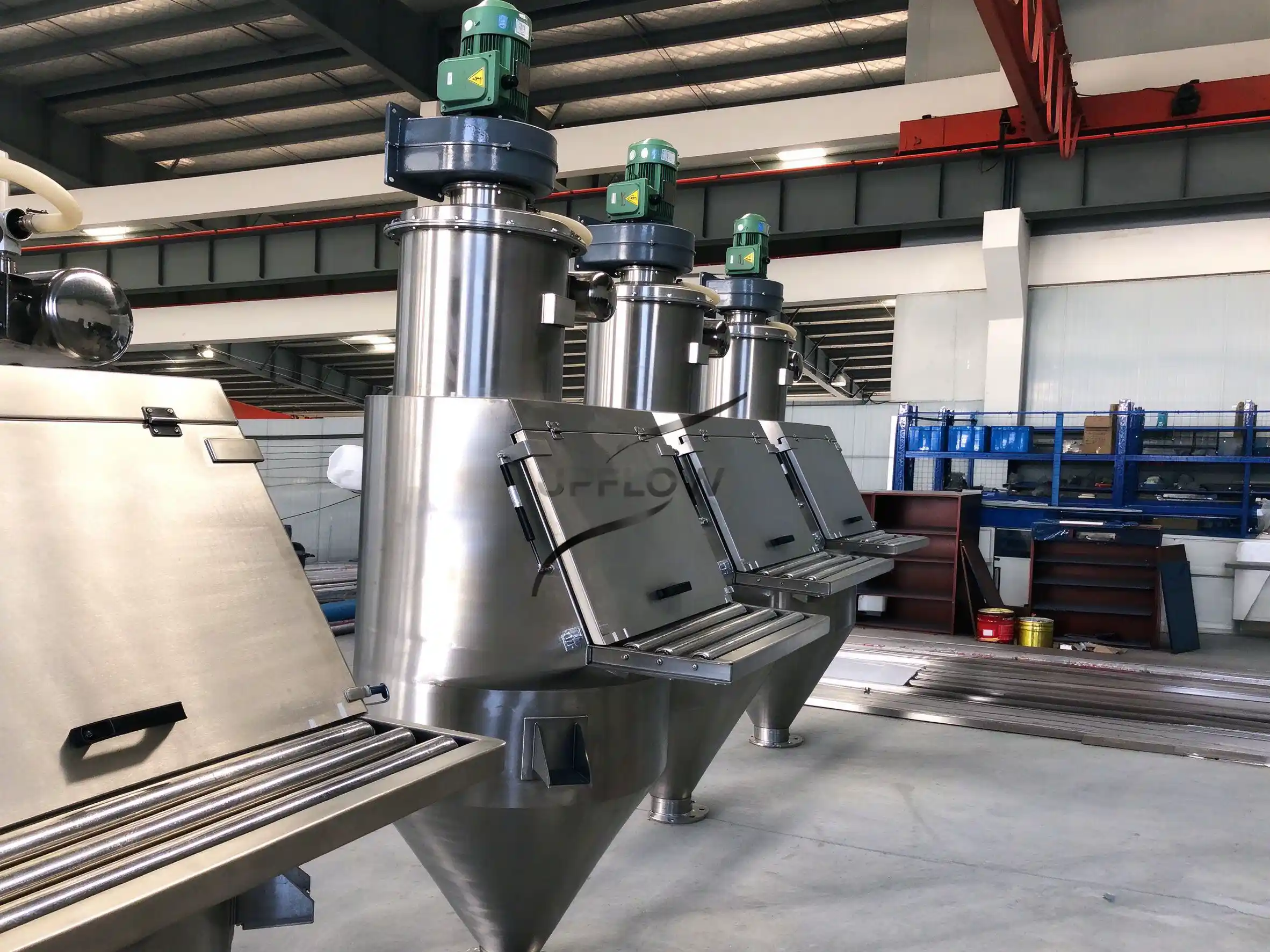
Chemical manufacturing processes frequently require powders, granules and other solid ingredients to be introduced into reactors, mixing tanks and processing vessels according to a defined production sequence, but transferring these materials from small bags into production equipment can create challenges involving dust emissions, manual handling, feeding accuracy and equipment integration.
A manual bag dump station provides a designated location for operators to open bags and introduce raw materials into a controlled feeding system, allowing the powder to enter a receiving hopper before being transferred to a reactor or mixing tank through gravity discharge, screw feeding or pneumatic conveying.
However, selecting a suitable manual bag dumping solution for reactor charging requires more than considering the feeding station itself, because the equipment layout, reactor inlet position, material characteristics, required batch quantity, dust containment and downstream process conditions must all be evaluated as parts of the same material handling system.
For chemical manufacturers handling additives, mineral powders, pigments, fillers and other solid ingredients, a properly designed bag dumping and reactor feeding arrangement can reduce unnecessary manual transfer operations while providing a more controlled connection between raw material preparation and the main production process.
1. Why Do Chemical Reactors and Mixing Tanks Need a Dedicated Bag Feeding System?
In many chemical production facilities, raw materials are delivered in 25 kg bags or other small packaging formats and must be introduced into reactors, blending vessels or mixing tanks before the next processing stage begins.
Traditional manual feeding may require operators to open bags near the production equipment and pour materials directly into the vessel, which can become increasingly difficult when the reactor inlet is elevated, the material generates considerable dust or several ingredients need to be added according to a specific batch recipe.
Common challenges include:
Powder dust escaping during bag opening and material charging.
Manual lifting and handling of bags near elevated reactor platforms.
Inconsistent ingredient quantities when operators estimate material additions manually.
Difficult connections between the bag dumping area and reactor charging inlet.
Material accumulation around the reactor charging opening.
Limited space for installing feeding and weighing equipment.
Additional cleaning requirements when different chemical formulations are processed.
Difficult coordination between powder feeding and the reactor’s operating sequence.
A dedicated manual bag dump station can provide a more organized location for introducing bagged materials, while the downstream equipment transfers the powder to the designated reactor or mixing tank.
UPFLOW’s Manual Bag Dump Station is designed for controlled manual discharge of powders and granules, with integrated dust collection and optional screening or magnetic separation, and can be configured with screw or vacuum conveying connections according to the application.
2. Typical Process Layout for Feeding a Reactor or Mixing Tank
The equipment arrangement should be determined according to the relative positions of the bag dumping station, receiving hopper and reactor inlet, because the required transfer height, horizontal distance and material feeding sequence directly influence the most suitable connection method.
A basic manual feeding arrangement may follow:
Manual Bag Dump Station → Receiving Hopper → Screw Feeder → Reactor or Mixing Tank
For installations requiring enclosed powder transportation, the process may instead use:
Manual Bag Dump Station → Vacuum Conveying System → Vacuum Receiver → Reactor Charging Inlet
For multi-ingredient chemical production, a weighing and batching stage may be added:
Manual Bag Dump Station → Feeding Hopper → Weighing Hopper → Controlled Discharge → Reactor or Mixing Tank
The main equipment components may include:
| Equipment | Main function | Design consideration |
| Manual bag dump station | Introduces bagged raw materials | Operator access and dust containment |
| Receiving hopper | Temporarily stores incoming powder | Volume and discharge geometry |
| Vibrating screen | Removes selected oversized particles | Screen aperture and capacity |
| Magnetic separator | Captures suitable ferrous contaminants | Magnetic strength and material compatibility |
| Screw feeder | Provides controlled material discharge | Feeding rate and flowability |
| Vacuum conveying system | Transfers powder through enclosed pipelines | Distance, elevation and conveying capacity |
| Weighing hopper | Measures ingredient quantities | Batch accuracy and load-cell arrangement |
| Reactor charging connection | Introduces powder into the vessel | Inlet dimensions and process interfaces |
| Dust collection system | Captures airborne powder | Extraction airflow and filtration |
Not every application requires all of these components, because a relatively simple chemical process may only need a manual feeding station and screw feeder, while a multi-ingredient production line may require weighing hoppers, automatic valves and a centralized control system.
3. How to Choose the Connection Method Between the Bag Dump Station and Reactor
The appropriate material transfer method depends on the reactor’s installation height, the distance from the feeding station, powder flowability, required feeding capacity and whether the process requires accurate batch dosing.
Three common configurations should be considered during the initial engineering stage.
3.1 Direct Gravity Feeding
Gravity feeding can be considered when the bag dump station is installed above the reactor inlet and the powder can move through a suitable chute or connecting hopper without requiring additional mechanical transportation.
This arrangement can reduce the number of moving components between the feeding station and the reactor, making the overall equipment configuration relatively straightforward.
However, the available vertical space must accommodate the operator working area, receiving hopper, connecting chute and reactor inlet, while the feeding structure should provide sufficient access for inspection and maintenance.
Gravity feeding may be suitable when:
The reactor is positioned below the feeding station.
The material has suitable flow characteristics.
The transfer route is short and relatively straightforward.
The process does not require complex intermediate weighing.
The factory has sufficient installation height.
For cohesive powders, the hopper and chute geometry should be evaluated carefully, because gravity alone may not provide stable discharge if bridging or material accumulation occurs.
3.2 Screw Feeder or Screw Conveyor Connection
A screw feeder can be considered when the bag dumping station and reactor inlet cannot be connected directly through gravity or when the process requires a controlled mechanical feeding rate.
The material is first introduced into a receiving hopper, after which a screw feeder transports the powder toward the reactor charging inlet.
A variable-frequency drive can be used to adjust the screw operating speed according to the feeding requirements, although accurate batch dosing requires an appropriate weighing or measurement arrangement rather than relying on motor speed alone.
Important design parameters include:
Screw diameter and conveying length.
Material bulk density and flowability.
Required feeding capacity.
Installation angle and discharge elevation.
Motor power and maintenance accessibility.
Sealing arrangement at the reactor connection.
Material retention and cleaning requirements.
For applications where the reactor receives several different ingredients, the screw feeding arrangement may also need to coordinate with weighing equipment and the production control system.
3.3 Vacuum Pneumatic Conveying Connection
Vacuum conveying is often worth evaluating when the reactor or mixing tank is located at a considerable distance from the bag dumping station or when powder needs to be transported through an enclosed pipeline to an elevated charging point.
In this arrangement, operators introduce the material through the manual bag dump station, after which the powder enters the vacuum conveying system and is transported to a receiver installed above or near the reactor.
The receiver can discharge the material into the reactor according to the production sequence through a suitable valve or feeding arrangement.
A typical configuration includes:
Manual bag dump station.
Vacuum conveying pickup connection.
Stainless steel conveying pipeline.
Vacuum receiver with filtration.
Discharge valve or controlled feeding device.
Reactor charging connection.
PLC control and process interlocks where required.
Vacuum conveying can reduce the need for manual powder transportation between different production areas, but the conveying system must be selected according to the powder properties, transfer distance, elevation, required capacity and receiving conditions.
Explore the UPFLOW Pneumatic Conveying System for more information about enclosed powder transfer solutions.
4. How to Control Ingredient Weighing and Batch Dosing
Chemical reactors frequently operate according to defined formulations, meaning that the quantity of each raw material must be controlled according to the production recipe rather than simply transferred into the vessel at an approximate rate.
For this reason, weighing and batching should be considered during the design of the bag dumping and reactor feeding system, especially when the process involves multiple powder ingredients or different target quantities.
4.1 Weighing Hopper Before Reactor Charging
A weighing hopper can be installed between the bag dumping station and the reactor to measure the quantity of powder before it enters the vessel.
The operating sequence may include:
Operators introduce the first powder through the manual bag dump station.
The powder enters the weighing hopper through a suitable feeding arrangement.
The weighing system monitors the material quantity.
Once the target weight is reached, the discharge valve opens.
The measured ingredient enters the reactor.
The process repeats for the remaining ingredients according to the recipe.
This arrangement provides a defined weighing point and can help separate raw material feeding from the final reactor charging operation.
4.2 Loss-in-Weight Feeding
For applications requiring controlled continuous or semi-continuous material addition, a loss-in-weight feeding arrangement may be considered, provided that the process conditions and equipment configuration support stable weighing measurements.
The feeding device is monitored through changes in hopper weight, allowing the control system to regulate material discharge according to the required feeding rate.
The suitability of this method depends on the material characteristics, weighing range, vibration isolation and operating sequence.
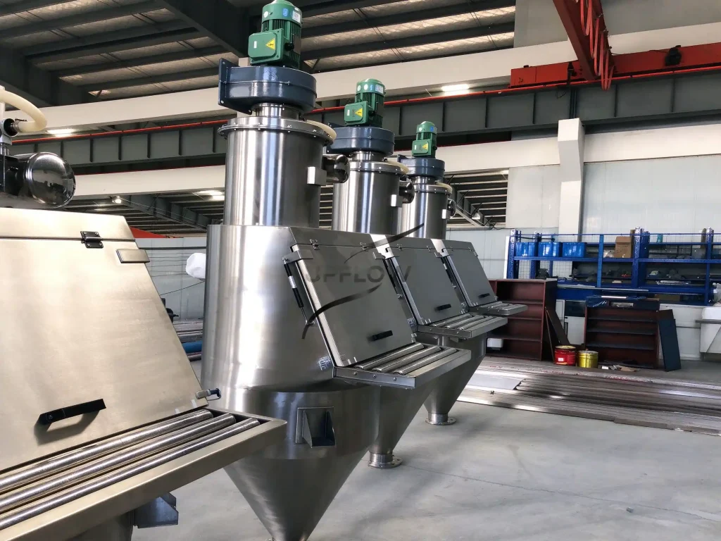
4.3 Automated Batching and Recipe Control
For chemical plants handling several raw materials, an integrated Automated Batching System can coordinate ingredient weighing, feeding sequence and reactor charging according to the defined production recipe.
The control system may include:
Ingredient identification.
Target weight settings.
Weighing and feeding control.
Valve operation and equipment interlocks.
Batch completion confirmation.
Communication with the plant’s central control system.
The weighing tolerance, load-cell specification and control interface should be confirmed according to the actual production requirements, rather than assuming that a standard batching arrangement can meet every chemical formulation.
For a practical example of integrated feeding, conveying and batching, see UPFLOW’s Magnesium Silicate Pneumatic Conveying System.
5. Dust Collection and Enclosed Reactor Charging
Dust control is particularly important when introducing fine chemical powders into reactors and mixing tanks, because airborne material may be generated during bag opening, powder discharge, conveying and reactor charging.
A complete feeding arrangement should consider the dust-generating points at both the manual bag dump station and the reactor inlet.
5.1 Dust Collection at the Bag Dump Station
The manual feeding station should provide a suitable enclosed working area and dust extraction connection to capture airborne powder generated during bag opening and tipping.
The extraction airflow should be determined according to the access opening, powder characteristics, operator movements, ductwork and filter resistance.
An appropriately configured dust collection system can help reduce powder release around the operator’s working area while maintaining a controlled material introduction process.
5.2 Dust Control at the Reactor Inlet
When powder enters a reactor, the incoming material may displace air or process gas inside the vessel, depending on the reactor’s operating conditions and charging arrangement.
The reactor inlet should therefore be evaluated together with the vessel’s venting, pressure and process safety requirements.
A dust extraction connection should not be added directly to a reactor without considering its operating pressure, atmosphere, venting arrangement and the requirements of the reactor manufacturer.
For example, a reactor operating under vacuum, positive pressure or an inert gas atmosphere may require a different charging and isolation arrangement from an atmospheric mixing tank.
5.3 Sealed Connections and Material Containment
The connection between the conveying receiver and reactor charging inlet should be designed to minimize material leakage during transfer and equipment disconnection.
Depending on the process, suitable components may include enclosed chutes, flexible connectors, isolation valves and controlled discharge devices.
The selected arrangement should also allow inspection, cleaning and maintenance without creating unnecessary exposure to residual powder.
For further technical guidance, read How to Reduce Dust Emissions in Pneumatic Conveying Systems.
6. Important Design Considerations for Chemical Reactors and Mixing Tanks
Although reactors and mixing tanks may both receive powders, their operating conditions are not necessarily identical, so the charging system should be selected according to the actual vessel configuration and process requirements.
6.1 Reactor Operating Pressure
One of the first questions is whether the reactor operates under atmospheric pressure, vacuum or positive pressure during material charging.
The feeding equipment, valves, flexible connections and vessel interface must be compatible with the intended operating conditions, and the reactor’s pressure boundary must not be compromised by an unsuitable feeding connection.
6.2 Temperature and Process Conditions
Some chemical processes involve elevated temperatures or specific operating atmospheres, which may influence the selection of flexible connectors, seals, valves and material-contact components.
The feeding system should be designed according to the conditions at the reactor charging interface rather than assuming that all powder feeding equipment operates at ambient temperature and atmospheric pressure.
6.3 Material Compatibility
Chemical powders may have different corrosion, moisture sensitivity, contamination and cleaning requirements, which influence the selection of equipment contact materials and surface finishes.
Stainless steel grades such as SUS304 or SUS316L may be considered depending on the chemical compatibility and customer requirements, but the final material selection should be confirmed against the actual chemicals and process conditions.
6.4 Hazardous and Combustible Dust Assessment
Certain chemical powders may present combustible dust, toxic exposure or other process safety hazards.
Where these risks exist, the feeding and dust collection arrangement may require additional assessment of grounding and bonding, explosion protection, electrical equipment suitability, ventilation and containment.
The exact requirements should be established through a site-specific hazard assessment and applicable regulations; a standard dust collector or enclosed hopper should not automatically be described as explosion-proof.
6.5 Cleaning and Cross-Contamination Control
When several chemical formulations are processed using the same feeding system, the equipment layout should provide suitable access for cleaning and inspection.
The hopper, screw feeder, receiver, pipelines and connecting components should be evaluated according to the required cleaning procedure, especially when the production process involves different ingredients or sensitive formulations.
7. Typical Equipment Configurations for Reactor Powder Feeding
Different chemical production lines may require different equipment arrangements according to the reactor position, number of ingredients and degree of automation.
| Application | Configuration to evaluate | Main engineering consideration |
| Simple powder charging | Bag dump station → hopper → gravity discharge → reactor | Elevation and material flow |
| Controlled mechanical feeding | Bag dump station → screw feeder → reactor | Feeding rate and discharge stability |
| Elevated reactor charging | Bag dump station → vacuum conveying → receiver → reactor | Transfer distance and receiver location |
| Multi-ingredient formulation | Bag dump station → weighing hopper → reactor | Batch accuracy and recipe control |
| Multiple reactors | Bag dump station → conveying network → selected receivers | Material routing and isolation |
| Fine or sensitive powders | Enclosed feeding → filtration → controlled reactor charging | Dust containment and material compatibility |
The final system configuration should be based on the customer’s production sequence and actual vessel drawings, rather than choosing equipment according to the reactor volume alone.
8. UPFLOW Project References: Integrated Chemical Powder Feeding
8.1 Magnesium Silicate Pneumatic Conveying and Batching Project
UPFLOW supplied a customized magnesium silicate powder conveying and batching system for an overseas industrial customer, integrating manual bag dumping, pneumatic conveying, weighing hoppers, screw feeding equipment, storage and centralized control.
The complete process connected the manual feeding point with enclosed powder transportation and downstream weighing and batching operations, providing a practical example of how different powder handling functions can be integrated according to a customer’s production requirements.
The project is relevant to chemical manufacturers considering a transition from separate manual powder charging operations toward a coordinated material feeding and batching arrangement.
Read more about the Magnesium Silicate Pneumatic Conveying and Batching System Project.
8.2 PVC Powder Feeding and Vacuum Conveying Project
For a new materials manufacturer, UPFLOW supplied a customized PVC powder feeding and vacuum conveying system that included bag unloading equipment, vacuum conveying units, stainless steel pipelines, receiving hopper modifications, dust collection connections and centralized electrical control.
The project involved transferring PVC powder from the bag unloading area to multiple downstream receiving points, with the equipment and pipeline arrangement developed according to the customer’s existing factory layout.
This project provides a relevant reference for chemical and materials manufacturers that need to connect a manual feeding station with remote production equipment through an enclosed conveying arrangement.
Read more about the PVC Powder Feeding and Vacuum Conveying System Project.
These projects demonstrate UPFLOW’s experience in customized powder feeding, pneumatic conveying and batching integration, but they should not be interpreted as projects that necessarily involved direct charging into a chemical reactor or mixing tank.
9. What Information Should Buyers Provide When Requesting a Reactor Feeding System?
Before preparing a quotation, the equipment supplier should understand the material characteristics, reactor configuration and required production sequence, because these factors determine the appropriate feeding method and connection arrangement.
| Information | Details to provide | Engineering purpose |
| Material name | Chemical powder or granular ingredient | Material compatibility assessment |
| Particle size | Particle size distribution | Feeding and conveying selection |
| Bulk density | Loose or settled bulk density | Hopper and capacity calculation |
| Material properties | Moisture, flowability and chemical characteristics | Equipment configuration |
| Bag dimensions | Packaging size and weight | Manual feeding station design |
| Reactor capacity | Working volume and batch quantity | Feeding and batching requirements |
| Reactor inlet | Inlet size, position and elevation | Connection design |
| Operating conditions | Atmospheric, vacuum or positive pressure | Isolation and sealing design |
| Feeding quantity | Required kg/batch or kg/h | Feeding equipment selection |
| Number of ingredients | Material types and recipe | Weighing and batching configuration |
| Factory layout | Distance and elevation | Equipment arrangement |
| Cleaning requirements | Cleaning method and changeover frequency | Equipment material and structure |
Providing the reactor general arrangement drawing, inlet details and material specifications can significantly improve the accuracy of the initial equipment proposal.
10. Frequently Asked Questions
Q1. Can a manual bag dump station feed powder directly into a chemical reactor?
Yes, when the reactor is positioned appropriately and the connection is designed according to the vessel’s operating conditions. Depending on the installation, powder may enter through gravity discharge, screw feeding or vacuum conveying, with suitable isolation and containment arrangements.
Q2. How do you transfer powder from a bag dumping station to an elevated reactor?
A vacuum conveying system can be considered when the reactor inlet is located above the feeding station or when the transfer route is relatively long. The powder is collected from the manual feeding point and transported through an enclosed pipeline to a receiver installed near the reactor charging inlet.
Q3. Does a reactor powder feeding system need a weighing hopper?
Not every application requires a separate weighing hopper, but one should be considered when ingredients must be added according to specific batch quantities or when manual quantity estimation cannot meet the required production accuracy.
Q4. How can dust be controlled during reactor powder charging?
Dust control may involve an enclosed bag dump station, local extraction, suitable filtration, enclosed conveying connections and a properly designed reactor charging interface. The system should also consider the reactor’s pressure and venting conditions to avoid creating an unsuitable process atmosphere.
Q5. Can one manual bag dump station supply multiple reactors?
Yes, a customized feeding and conveying network can be designed to supply several receiving points, provided that material routing, isolation valves, conveying capacity, equipment interlocks and cleaning requirements are properly coordinated.
Q6. Which stainless steel material is suitable for chemical powder feeding equipment?
SUS304 and SUS316L are commonly considered for industrial powder handling equipment, but the appropriate grade depends on the actual chemical composition, moisture, temperature, cleaning agents and corrosion conditions. Material compatibility should be verified before fabrication.
Q7. What is the difference between reactor feeding and mixing tank feeding?
Both processes introduce ingredients into a vessel, but a chemical reactor may have additional requirements involving operating pressure, temperature, inert atmosphere, venting and process safety. A mixing tank may have a simpler charging arrangement in some applications, although its actual configuration must still be evaluated according to the process conditions.
Conclusion: Design Reactor Powder Feeding Around the Complete Process
A reliable manual bag dump station for feeding reactors and mixing tanks should be designed according to the complete material handling and production sequence, because the relationship between bag opening, receiving hoppers, conveying equipment, weighing systems and reactor charging connections determines whether powder can be introduced in a controlled and consistent manner.
Gravity feeding may be appropriate for simple installations with sufficient vertical clearance, while screw feeders and vacuum conveying systems can provide greater flexibility when the reactor is installed remotely or at a different elevation; for multi-ingredient chemical production, a suitable weighing and batching arrangement should also be considered to ensure that each ingredient enters the vessel according to the required production recipe.
UPFLOW provides customized manual bag dump stations, pneumatic conveying systems, automated batching equipment and integrated powder handling solutions according to material characteristics, chemical process requirements and factory layouts.
Planning a powder feeding system for a chemical reactor or mixing tank? Send UPFLOW your material specifications, reactor drawings, required batch quantities and factory layout so that our engineering team can evaluate a suitable feeding and connection arrangement.
Explore the UPFLOW Manual Bag Dump Station, the Pneumatic Conveying System or contact our engineering team to discuss your project requirements.