
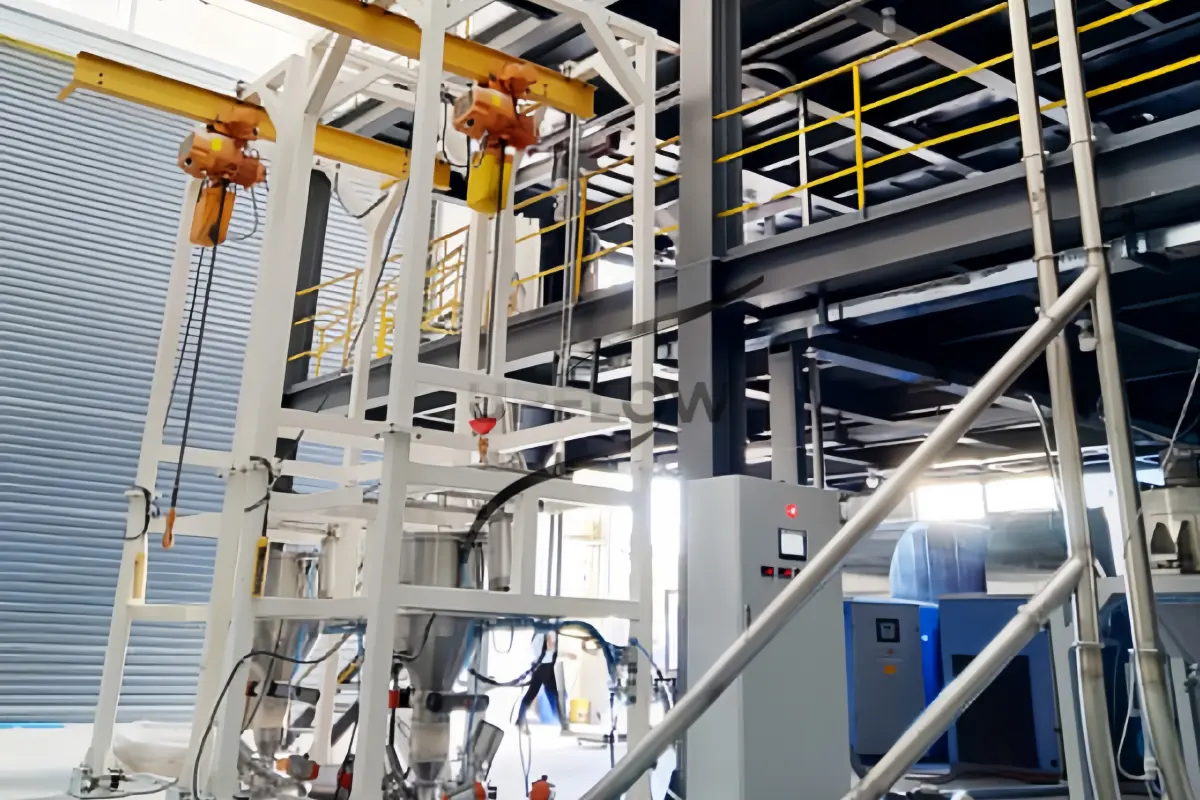
Planning the footprint and ceiling height of a bulk bag unloading station is an important step in industrial powder handling projects, because the available installation space must accommodate not only the unloading equipment itself but also the suspended FIBC bag, lifting mechanism, operator access, dust collection equipment and downstream material transfer connections. An unloading station that fits within the available floor area may still be unsuitable if the building does not provide sufficient overhead clearance for lifting and positioning a fully loaded bulk bag, or if there is insufficient space for bag replacement, equipment maintenance and connection to the production line.
For this reason, the required installation dimensions should be determined from the complete unloading process rather than from the external dimensions of the machine alone. The final layout should consider the actual FIBC dimensions, bag loading method, unloading structure, material characteristics, required capacity and the equipment connected below the discharge outlet.
1. What Determines the Footprint of a Bulk Bag Unloading Station?
The footprint of a bulk bag unloading station refers to the floor area required for installing and operating the equipment, including the supporting frame, bag positioning area, unloading section and any auxiliary components that form part of the complete installation.
Although different manufacturers may offer standard equipment configurations, industrial bulk bag unloading stations are frequently customized because the required space depends on the customer’s packaging specifications, material handling process and factory layout.
The following factors should be considered during the initial layout design.
1.1 FIBC Bag Dimensions and Loading Capacity
The dimensions and weight of the bulk bag directly influence the size of the supporting frame and the available space required for positioning the bag above the discharge connection.
For example, a facility handling standard one-ton FIBC bags may have different structural requirements from a production line using larger-capacity bags or bags with non-standard dimensions, particularly when the unloading station needs to accommodate different bag sizes within the same production area.
Before finalizing the equipment footprint, buyers should provide the following information:
FIBC bag length, width and filled height.
Maximum gross and net bag weight.
Lifting loop arrangement and lifting height.
Discharge spout diameter and length.
Inner liner construction, if applicable.
Number of different bag specifications used in production.
The equipment manufacturer can then determine the supporting frame dimensions, lifting arrangement and discharge interface according to the actual packaging conditions.
1.2 Bag Loading Method: Hoist or Forklift
The method used to load FIBC bags is another important factor affecting the installation footprint.
An electric hoist or overhead lifting arrangement generally requires a suitable lifting structure and enough vertical clearance to raise and position the filled bag above the unloading station, while a forklift-loaded arrangement requires sufficient floor space for vehicle access, pallet positioning and safe maneuvering around the equipment.
| Design consideration | Hoist-mounted arrangement | Forklift-loaded arrangement |
| Bag loading | Electric hoist or lifting device | Forklift |
| Overhead clearance | Requires lifting and positioning clearance | Depends on forklift mast and bag lifting height |
| Floor space | May reduce forklift maneuvering requirements | Requires vehicle access and operating space |
| Building structure | Supporting structure and lifting load must be evaluated | Floor condition and forklift access must be checked |
| Typical consideration | Fixed unloading stations and regular bag replacement | Facilities with existing forklift material handling |
Neither arrangement is universally better, because the suitable option depends on the factory layout, existing material handling equipment, available lifting infrastructure and operating frequency.
1.3 Supporting Frame and Auxiliary Equipment
The footprint should include all components required for the unloading operation rather than only the central supporting frame.
Depending on the system configuration, these components may include:
Bulk bag supporting frame and lifting structure.
Bag unloading chamber and discharge connection.
Pneumatic bag-clamping or squeezing devices.
Receiving hopper and intermediate storage hopper.
Dust collector and connecting ducts.
Screw feeder or rotary valve.
Electrical control cabinet and pneumatic control components.
For example, if the unloading station includes a receiving hopper and screw feeder underneath the discharge section, the overall equipment height and maintenance clearance will be different from those of a basic unloading frame.
The layout should therefore be prepared using the complete equipment arrangement and its actual connection points.
2. How Much Ceiling Height Is Required for a Bulk Bag Unloader?
The required building height depends primarily on the maximum lifting envelope, the dimensions of the filled FIBC bag, the height of the unloading structure and the clearance required for positioning and connecting the bag.
There is no single ceiling height that is suitable for every bulk bag unloading station, because a hoist-mounted system, a forklift-loaded system and a low-profile unloading station can have significantly different vertical space requirements.
A practical way to evaluate the required height is to divide the installation into several vertical sections.
2.1 Calculate the Vertical Lifting Envelope
For an overhead hoist arrangement, the available building height must accommodate the lifting device, hook or lifting attachment, filled bag and the space needed to position the bag above the unloading connection.
The preliminary calculation can be expressed as:
Required Building Height = Lifting Equipment Height + Maximum Bag Lifting Envelope + Unloading Station Height + Installation and Operating Clearance
This is a conceptual layout calculation rather than a fixed equipment specification, and the exact reference points should be established using the selected hoist, lifting arrangement and approved equipment drawing.
When checking the vertical envelope, engineers should also consider the lifting hook’s highest and lowest operating positions, the position of the bag lifting loops and whether the bag can be aligned with the discharge spout without interfering with the equipment frame.
2.2 Consider the Filled Bag Height and Deformation
The filled height of an FIBC bag can vary according to its rated capacity, filling density, fabric construction and material characteristics, meaning that the actual bag dimensions should be used instead of assuming that every one-ton bag has an identical shape.
In addition, some bags may change shape during transportation and storage, so the design should provide enough space for the actual bag to be lifted and positioned without interference from beams, lighting fixtures, pipes or other building services.
2.3 Check Overhead Structural and Building Obstructions
The nominal building ceiling height does not necessarily represent the usable lifting height, because structural beams, ventilation ducts, cable trays, fire protection pipelines and lighting fixtures may occupy part of the available vertical space.
For a hoist-mounted bulk bag unloading station, the engineering team should check the lowest overhead obstruction within the complete lifting and bag positioning area, not just the height directly above the center of the machine.
If the facility has limited headroom, a customized low-profile arrangement or an alternative bag loading method may be worth evaluating before the equipment structure is finalized.
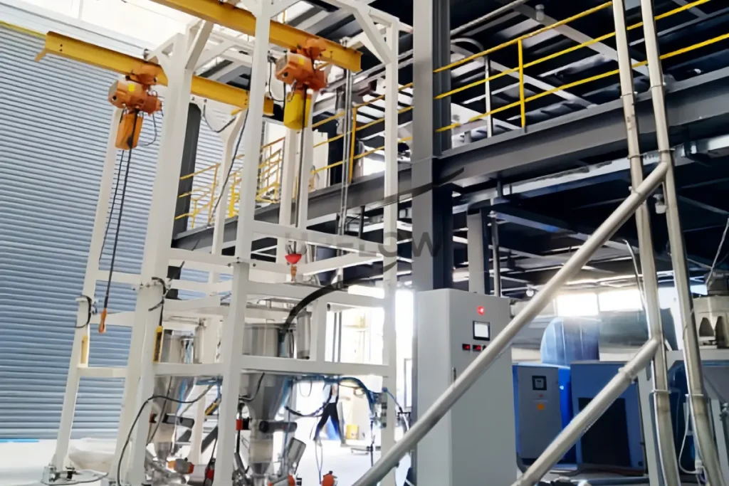
3. Additional Space Requirements Around the Unloading Station
A bulk bag unloading station requires additional working and maintenance space beyond its equipment footprint, because operators need to load bags, connect discharge spouts, monitor the unloading process and remove empty bags.
The following areas should be included in the factory layout.
3.1 Bag Loading and Replacement Area
The loading area should provide enough room for the selected lifting equipment or forklift to position the FIBC safely, while the arrangement should also allow the operator to access the lifting loops and discharge spout without unnecessary manual handling.
For facilities using pallets, the layout should consider the position of incoming full bags and the temporary storage area for empty pallets, ensuring that these activities do not obstruct access to the unloading station.
3.2 Operator Access and Working Clearance
Operators need sufficient access to inspect the bag connection, operate the unloading controls and monitor the discharge process, so the surrounding layout should avoid placing electrical cabinets, pipes or other equipment directly in front of frequently used access points.
The actual working clearance should be determined according to the operating procedure, equipment access doors, bag handling method and applicable workplace safety requirements.
3.3 Maintenance and Filter Replacement Space
If the unloading station includes a dust collector, filter elements and cleaning mechanisms may require additional access space for inspection and replacement.
The same consideration applies to pneumatic cylinders, rotary valves, screw feeders and electrical components, because a layout that makes routine maintenance difficult can increase equipment downtime even when the original installation fits within the available factory space.
A maintenance review should therefore identify the components that need to be removed or opened and confirm that the necessary access space is available after all surrounding equipment has been installed.
4. How Downstream Equipment Affects the Overall Layout
The receiving equipment installed underneath the bulk bag unloading station can significantly influence the overall height, footprint and connection arrangement.
For applications where the discharged powder is transferred directly into downstream production equipment, the unloading station should be designed together with the feeding and conveying system.
| Downstream equipment | Layout consideration | Typical application |
| Receiving hopper | Hopper volume, discharge height and supporting structure | Temporary powder storage |
| Screw feeder | Motor access, feeder length and feeding outlet | Controlled powder feeding |
| Rotary valve | Installation height and maintenance access | Regulated discharge and pneumatic conveying interfaces |
| Weighing hopper | Load-cell installation and structural isolation | Batch feeding and weighing |
| Pneumatic conveying system | Pipeline routing, air supply and receiving equipment | Transfer to remote silos or production equipment |
| Mixer or reactor | Connection height, feeding sequence and access | Direct material charging |
For example, a bulk bag unloading station connected to a screw feeder and pneumatic conveying system may require a taller installation arrangement than a standalone unloading station, because the downstream equipment and pipeline connections must also be accommodated.
When multiple materials are handled in the same production area, the design should additionally consider the positions of the different receiving hoppers, material changeover arrangements and the possibility of cross-contamination during equipment cleaning.
For more information about integrated equipment configurations, see UPFLOW’s Bulk Bag Unloading and Conveying System Guide.
5. Bulk Bag Unloading Station Layout Checklist
Before requesting a quotation or approving the equipment layout, buyers should prepare the following information so that the manufacturer can evaluate the available installation space and identify potential interference before fabrication begins.
| Item | Information to provide | Design purpose |
| Factory floor area | Available length and width | Confirm equipment footprint |
| Building height | Floor-to-ceiling and lowest beam height | Evaluate lifting clearance |
| FIBC dimensions | Length, width and filled height | Determine frame and bag positioning |
| Bag weight | Maximum filled bag weight | Evaluate lifting and support requirements |
| Loading method | Hoist, forklift or other lifting arrangement | Determine access and operating envelope |
| Floor conditions | Foundation, floor loading and level | Evaluate equipment installation |
| Dust collection | Collector location and duct routing | Reserve auxiliary equipment space |
| Downstream equipment | Hopper, feeder, mixer or silo | Determine total system height |
| Utilities | Electrical and compressed air connections | Reserve connection access |
| Maintenance | Filter replacement and component removal | Ensure serviceability |
A factory layout drawing showing columns, beams, existing equipment, access doors and available utility connections is particularly useful because it allows the equipment supplier to evaluate the complete installation area rather than estimating the equipment position from floor dimensions alone.
6. Real Bulk Bag Unloading Project References
Actual industrial projects provide useful references for understanding how bulk bag unloading equipment is integrated into different production environments, although the dimensions and equipment arrangements of one project should not automatically be applied to another facility.
6.1 European Battery Material Manufacturer: Multiple Anode Material Unloading Systems
UPFLOW supplied multiple customized big bag unloading systems for a European battery material manufacturer, providing an enclosed feeding arrangement for anode material handling and integration with the customer’s downstream material transfer process.
The project demonstrates the importance of considering bulk bag positioning, controlled powder discharge, dust collection interfaces and downstream equipment connections together when planning unloading systems for battery material production.
Read more about the Anode Material Big Bag Unloading System Project.
6.2 Cement Big Bag Unloading and Pneumatic Conveying Project in Egypt
For an industrial customer in Egypt, UPFLOW supplied a customized cement big bag unloading and pneumatic conveying solution integrating bulk bag unloading equipment, powder feeding and enclosed material transportation.
This project illustrates how the unloading station can be designed as the upstream section of a larger powder handling line, where the installation arrangement needs to accommodate not only the unloading frame but also the feeding and conveying equipment connected to it.
Read more about the Cement Big Bag Unloading and Pneumatic Conveying Project.
These project references demonstrate UPFLOW’s experience in customized bulk bag unloading and integrated powder handling equipment, while the final equipment footprint and building clearance must still be determined from each customer’s actual drawings and process requirements.
7. Frequently Asked Questions About Bulk Bag Unloading Station Dimensions
Q1. What is the standard footprint of a bulk bag unloading station?
There is no universal standard footprint that applies to all bulk bag unloading stations, because the required floor area depends on the FIBC dimensions, loading method, equipment configuration, auxiliary components and downstream process connections. Buyers should request a layout drawing based on their actual installation conditions.
Q2. How high should a factory ceiling be for a bulk bag unloader?
The required building height depends on the lifting arrangement, filled bag dimensions, hoist operating envelope, equipment frame and installation clearance. The lowest overhead obstruction should be considered when calculating the usable lifting height rather than relying only on the nominal ceiling height.
Q3. Can a bulk bag unloading station be installed in a factory with limited space?
Yes, a customized layout may be possible depending on the available floor area and vertical clearance. Possible options include changing the bag loading method, reducing unnecessary auxiliary equipment space or arranging the downstream equipment differently, provided that bag handling, maintenance access and operating requirements remain acceptable.
Q4. Does a forklift-loaded bulk bag unloader require less ceiling height?
A forklift-loaded arrangement may avoid the need for an overhead hoist installation, but the required height still depends on the forklift mast, lifting height, bag dimensions and supporting frame. The complete operating envelope must be checked before selecting this arrangement.
Q5. Should the dust collector be included in the equipment footprint?
Yes, when the dust collector is supplied as part of the unloading station, its installation position, filter replacement access and connecting ductwork should be included in the overall layout. If the collector is installed separately, the connection route and maintenance space should still be considered.
Q6. What drawings should buyers provide before requesting a customized layout?
Buyers should ideally provide the factory floor plan, building height and beam positions, FIBC bag drawings, loading method, material information and downstream equipment arrangement. These details help the supplier prepare a more realistic equipment layout and identify installation conflicts before manufacturing.
Conclusion: Plan the Complete Installation Space Before Selecting a Bulk Bag Unloader
The footprint and ceiling height requirements of a bulk bag unloading station should be determined by evaluating the complete operating process, including FIBC lifting, bag positioning, controlled discharge, dust collection, operator access, maintenance and downstream material transfer.
For industrial manufacturers planning a new powder handling line or upgrading an existing production facility, providing the supplier with the actual factory layout and FIBC specifications at the beginning of the project can help reduce installation conflicts and avoid unnecessary modifications after equipment delivery.
UPFLOW provides customized bulk bag unloading systems, powder feeding equipment, dust collection arrangements and pneumatic conveying solutions according to material characteristics, production requirements and factory installation conditions.
Planning a new bulk bag unloading station? Send UPFLOW your available floor dimensions, building height, FIBC bag specifications and required unloading capacity so that our engineering team can evaluate a suitable equipment arrangement.
Explore the UPFLOW Bulk Bag Unloading System or contact our engineering team to discuss your installation requirements.