
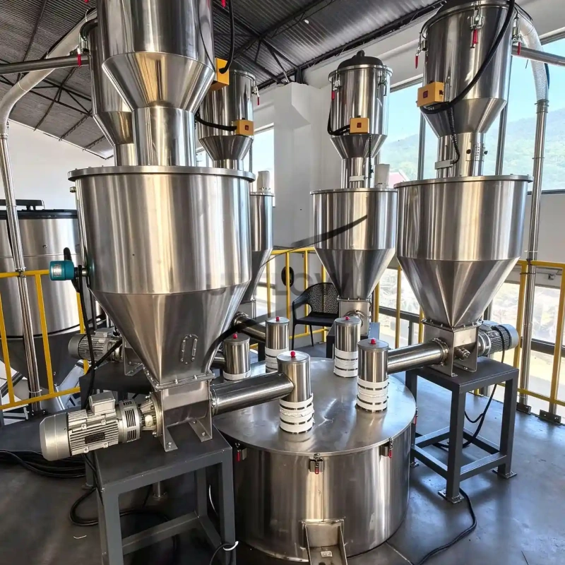
Retrofitting a Vacuum Receiver to an Existing Hopper: Interface Checklist
Before fitting a vacuum receiver to an existing hopper, verify the support load path, connection geometry, discharge clearance, vessel pressure limits and control handshakes. Matching the inlet diameter is only one part of the retrofit. A receiver can fit the opening yet overload the lid, obstruct maintenance or discharge into a vessel that cannot accept the batch.
This checklist concerns the receiver-to-hopper interface. For the wider operating principle, see our negative-pressure pneumatic conveying guide. The completed checklist should be reviewed against the actual equipment drawings before an installation is approved.
Gather the existing-equipment information first
Obtain the hopper drawing, inlet and lid details, current support arrangement, allowable loads and pressure conditions. Take dimensioned photographs showing overhead beams, adjacent pipes, platforms and the access route. Record the receiving material, batch behaviour and any weighing system below the hopper.
If original drawings or ratings are unavailable, identify that gap explicitly. A photograph or nominal flange size cannot establish structural adequacy or pressure capability. Have the responsible equipment owner or engineer confirm those conditions before ordering an adapter.
Complete the retrofit interface checklist
Use the pneumatic conveying component guide to identify which items belong to the receiver, the existing hopper and the wider line.
| Review point | Evidence to obtain | Decision to record |
|---|---|---|
| Connection | Opening dimensions, flange pattern, seal location and outlet position | Direct connection, engineered adapter or revised layout |
| Support | Receiver mass, maximum retained material, attachments and operating loads | Verified hopper support or a separately designed structure |
| Discharge | Valve movement envelope, drop path and maximum receiving level | Unobstructed discharge with high-level protection |
| Pressure and air | Permitted hopper conditions, equalisation sequence and displaced-air route | Confirmed pressure boundary and appropriate vent arrangement |
| Service access | Filter removal path, lifting needs, platforms and isolation access | Maintainable without dismantling unrelated equipment |
| Weighing | Location of load cells, rigid connections, hose forces and refill timing | Connection arrangement and weighing acceptance procedure |
| Control signals | Demand, ready, full, valve confirmation and fault handling | Agreed cause-and-effect table and responsibility split |
Separate the support path from the material path
When comparing UPFLOW pneumatic conveying systems, ask the supplier to mark the equipment boundary and support responsibilities on the proposed layout.
The outlet can align with the hopper opening while the receiver is carried by an independent frame. Alternatively, the receiving vessel may be designed to carry the assembly. Choose the arrangement from verified loads and drawings, not from appearance.
The review should include the receiver, the maximum retained product and attached pipework or accessories. Also identify operating effects that the responsible designer requires in the load assessment. An adapter modifies geometry; it does not increase the rating of the existing lid. Document who supplies the support, adapter, seals and installation work.
Define the pressure boundary and discharge sequence
In a batch vacuum arrangement, material is collected during suction and released during a separate discharge step. Confirm the actual sequence and valve behaviour for the proposed equipment rather than assuming all receivers work identically.
Identify which vessel sees vacuum, when equalisation occurs, and what happens if a discharge valve fails to close. Do not presume that an existing atmospheric hopper can withstand vacuum. During product discharge, establish where displaced air goes; a tightly connected lid may change a previously open receiving arrangement.
Show any vent or extraction connection on the drawing and state its design responsibility. The final arrangement must account for the material’s handling requirements and the plant’s applicable protection design. A receiver seal is not a substitute for this review.
Leave access for the next filter change
Measure the space required to remove the actual filter assembly, open clamps and operate lifting equipment. Check the valve’s full movement and access to its actuator. Include a safe method for isolation and cleaning in the maintenance plan.
Ask the supplier to mark these envelopes on the arrangement drawing. A useful review includes both the installed position and the service position, plus the route by which a removed part reaches the platform or floor.
Write the control handshakes before commissioning
A retrofit needs agreement on which controller owns each decision. For example, the plant requests refill, the receiver checks its own readiness, and discharge requires permission from the receiving equipment. The exact logic is application-specific; document it as an agreed cause-and-effect table rather than relying on a verbal description.
During witnessed checks, simulate no demand, receiving high level, source empty and loss of a required valve confirmation. Record the expected response and restoration procedure. Measure the complete delivery cycle using the batch-cycle capacity method when refill timing matters.
Installed-project reference
The Korea vacuum powder-feeding project provides a separate reference for discussing vacuum-feeding equipment and its downstream interfaces. It does not establish the suitability of your existing hopper or document this particular retrofit.
Watch the vacuum feeding sequence
UPFLOW’s animation below illustrates bag feeding, enclosed transfer and receivers above downstream vessels. It is a general vacuum-feeding illustration, not footage of a flour installation or a verified retrofit. Use it to discuss equipment interfaces; it does not establish capacity, food-contact suitability or the required protection design.
Watch Vacuum Feeding System on UPFLOW’s YouTube channel.
FAQ
Can a flexible connector protect hopper weighing?
It may help accommodate movement, but stiffness, misalignment and pressure forces can still influence the measurement. Review all connections and verify weight behaviour under the actual refill conditions.
Must the existing hopper be replaced?
Not necessarily. An engineered support or revised interface may be feasible. The decision depends on verified vessel condition, loading, pressure limits, discharge and access requirements.
What is the most useful document for comparing retrofit quotations?
A marked-up interface drawing with a responsibility table: receiver, adapter, support, venting, utilities, controls, installation and acceptance checks. Confirm every exclusion rather than comparing only the receiver price. Attach the completed RFQ datasheet so suppliers work from the same material, route and delivery requirements.
Send the interface details with your enquiry
Send your hopper drawing, interface dimensions and completed review sheet, then contact UPFLOW to discuss the retrofit scope.