
Sizing Batch Vacuum Conveying Capacity from the Full Operating Cycle
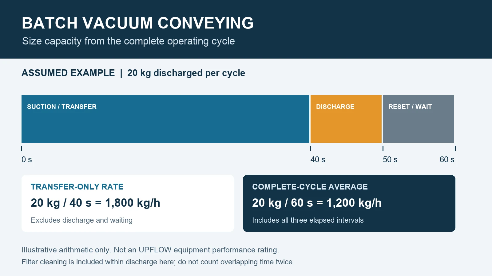
Illustration: an assumed batch cycle, showing why transfer time alone is not a plant throughput rating.
Batch vacuum conveying capacity is the mass actually discharged per complete cycle multiplied by the number of cycles completed per hour. A transfer rate measured only while powder moves through the pipe excludes discharge, valve sequencing and waiting for the receiving equipment. Use the complete operating cycle when specifying how reliably a mixer, feeder or process hopper must be supplied.
This guide provides a cycle worksheet and a clearly labeled calculation example. It complements our negative pressure conveying overview; it is not a capacity rating for a particular UPFLOW conveyor or powder.
Define the delivery requirement before selecting the receiver
Write the requirement at the point where usable material enters the downstream process. State the material grade, required kilograms per hour, mass per refill, maximum permitted refill time, and whether production consumes material while the conveying receiver is loading. A process needing occasional large batches can have the same hourly demand as a continuously consuming feeder but a very different refill constraint.
Keep three rates separate: the mass transfer rate during suction, the average rate across repeated operating cycles, and the delivered rate across a shift including interruptions. Also state whether the measurement counts all transferred material or only acceptable product after losses and quality checks.
Record the full batch vacuum conveying cycle
Start and stop the timer at the same repeatable event, such as the start of suction on successive cycles. Log the actual discharged mass over multiple cycles. The worksheet below describes possible activities; it does not prescribe a universal control sequence.
| Activity | What to record | Counting rule |
|---|---|---|
| Feed preparation | Time until material is available at the pickup; bag replacement or source change | Count only the part that delays the next cycle; upstream preparation may overlap |
| Suction and transfer | Suction start/end, pickup stability and receiver fill endpoint | Include any startup delay within this timed interval |
| Separation and line clearing | Separation during loading; any separate clearing or settling step | Separation normally occurs during transfer; add only additional sequential time |
| Discharge and filter cleaning | Valve sequence, complete emptying and cleaning timing | If cleaning overlaps discharge, use the elapsed combined interval |
| Reset and waiting | Valve confirmation, demand signal, high-level interlock and readiness | Count elapsed time before the next suction start |
For context, Piab’s explanation of cyclic vacuum conveying describes loading into a receiver, followed by discharge, with filter cleaning occurring during discharge. This illustrates why overlapping activities must not simply be added together. Confirm the actual sequence for the proposed equipment.
Calculate average capacity using mass and elapsed time
Cycle-average capacity (kg/h) = 3,600 × discharged mass per cycle (kg) ÷ complete cycle time (seconds).
For variable cycles, use total discharged mass divided by total elapsed time, then convert to kg/h. Averaging individual cycle rates can distort the answer when cycle durations differ. Record material left in the receiver separately if the weighed quantity is inlet mass rather than discharged mass.
Worked example — assumed values, not test results
Assume a batch system discharges 20 kg per cycle. Suction takes 40 seconds. A combined discharge/filter-cleaning interval takes 10 seconds, and reset plus process waiting takes another 10 seconds. These three intervals are assumed to be sequential and non-overlapping, giving a 60-second cycle.
- Transfer-only rate: 3,600 × 20 ÷ 40 = 1,800 kg/h.
- Complete-cycle average: 3,600 × 20 ÷ 60 = 1,200 kg/h.
- If the defined shift includes an additional 10% stopped time outside those cycles, its calculated average becomes 1,200 × 0.90 = 1,080 kg/h.
The 1,800 kg/h number would overstate this example’s complete-cycle delivery by 50%. Do not apply the additional availability factor if the same stoppages are already inside the measured elapsed time. All example values are assumptions for arithmetic only; actual capacity requires material, route and equipment verification.
Check the receiver and downstream refill window
A vessel’s nominal volume is not necessarily its usable batch volume. Freeboard, filters, level detection, material aeration and complete discharge affect the usable quantity. For an initial mass-volume check, batch mass equals usable material volume multiplied by the applicable bulk density. Specify the density and fill condition rather than converting from liters with an unexplained factor.
A continuous process also needs enough usable buffer inventory while the conveying receiver is unavailable. Compare material consumption over the longest expected refill interval with usable buffer stock. Check the instantaneous discharge into that buffer: an acceptable hourly average does not prove that a narrow inlet or vent can accept a rapid batch dump.
When several receiving points share a source or conveying resource, include changeover and time spent serving other destinations. Simultaneous peak demands need a schedule or separate resources; adding individual nameplate capacities does not establish network delivery.
What to verify before accepting a capacity proposal
- Material: grade, bulk-density range, particle-size distribution, moisture, flow behavior and acceptable degradation.
- Route: horizontal run, vertical lift, bends, pickup arrangement and the destination used for the capacity assessment.
- Utilities: available air or electrical conditions at the equipment during operation, with the measurement boundary stated.
- Evidence: discharged mass, cycle timestamps, repeated-cycle duration, filter condition, interruptions and downstream demand state.
- Acceptance boundary: delivered throughput, product quality, complete emptying, containment and agreed operating conditions.
UPFLOW’s PVC powder feeding and vacuum conveying project illustrates why receiving-hopper interfaces, level detection and coordinated control belong in the system scope. The project page is an integration reference; it does not supply the timing or capacity data used in the assumed example above.
Frequently asked questions
Can I size the system from suction time alone?
No. Suction time gives a transfer-only rate. Include all elapsed time between repeated cycle boundaries, then check the downstream refill deadline and any shift interruptions outside that boundary.
Will a larger vacuum receiver always increase throughput?
No. A larger usable batch may reduce the frequency of discharge, but pickup, line resistance, filter loading, emptying time and downstream acceptance can still limit delivery. Evaluate the complete sequence with the actual material.
Is a batch vacuum conveyor a weighing feeder?
Not automatically. A timed or level-controlled receiver does not by itself establish batch weighing accuracy. Define whether the process requires transfer, inventory refill or a controlled weighed dose and specify the necessary weighing and control arrangement separately.
Send a cycle-based conveying enquiry
Review the UPFLOW vacuum feeding system, then send your material details, route drawing, demand pattern, batch mass and available refill window. Use our pneumatic conveying RFQ datasheet to keep the inputs organized, or request an application review with the operating conditions attached.