
Vacuum Refill and Weighing: Planning a Stable Measurement Window
When vacuum conveying refills a weighing hopper, define when material enters, which mechanical or pressure effects change, and when the weight can be accepted for the control duty. Do not treat a moving weight signal during refill as the same measurement used after a batch has settled.
Start by distinguishing batch weighing from continuous loss-in-weight feeding. The automated batching system and conveying controls should specify which device owns refill, measurement validity and release. The right sequence depends on that arrangement.
Distinguish two different weighing arrangements
In a batch weigh-and-release arrangement, incoming material is accumulated and the accepted batch weight is evaluated in the agreed state before downstream release. A continuous loss-in-weight feeder instead uses a decreasing weight trend to control delivery. During refill its net weight increases; the normal depletion signal alone cannot describe the simultaneous output.
The continuous feeder may use a controller-specific refill mode. Confirm that mode with the actual feeder supplier; the batch sequence illustrated here is not a programme for continuous gravimetric feeding. Our conveying and batching integration guide explains the broader package boundary.
Record disturbances before adding a delay
Capture the weight trend together with refill request, vacuum-source state, receiver discharge and relevant valve events. Check whether the apparent weight change follows actual incoming material, a pressure event, vibration or force through a connected pipe or flexible connector.
Pressure changes at a connected inlet or outlet can affect the weighing signal. A flexible connection also needs an appropriate installation; its presence alone does not prove mechanical isolation. Review these interfaces with the equipment owners rather than masking an unexplained trend with a longer timer.
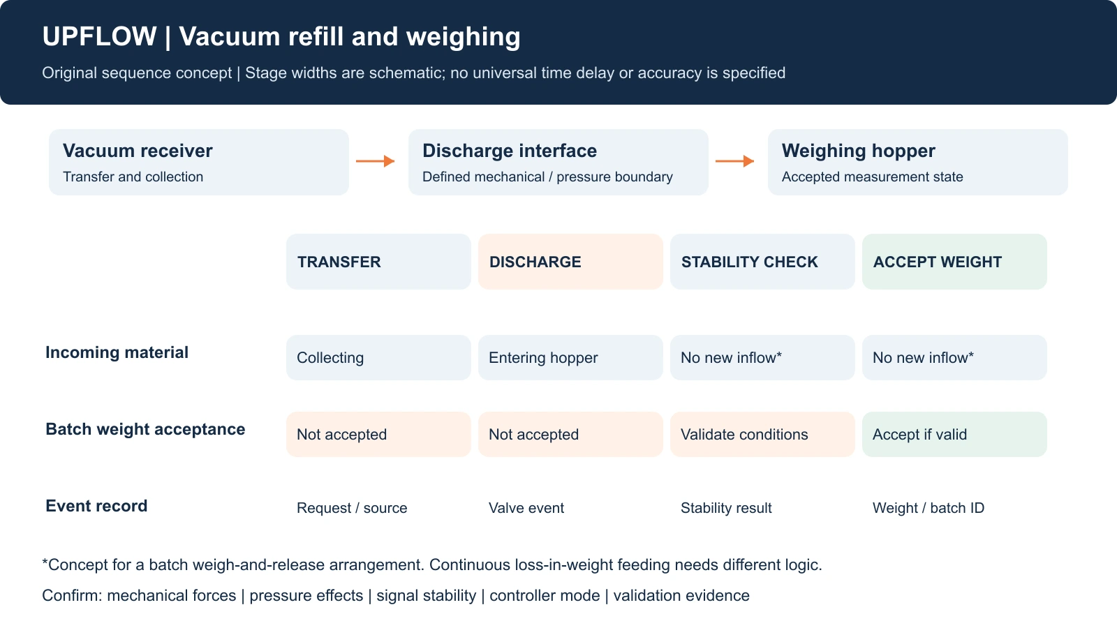
A batch measurement window, shown as a sequence concept
The illustration and worksheet are original planning tools. Their stage widths are schematic and contain no universal settling time. They assume a batch weigh-and-release duty in which further inflow is excluded during the accepted measurement state. Confirm the physical arrangement before adopting that assumption.
| Stage | What to verify | Evidence to retain |
|---|---|---|
| Vacuum transfer | Where collected material resides and whether it affects the weighing boundary | Vacuum state and receiver event log |
| Receiver discharge | Inflow path, valve state and relevant mechanical/pressure interactions | Discharge event and weight trend |
| Stability check | Required inflow/connection state and validated signal-stability criterion | Status signals and observed stability result |
| Accept weight | Measurement valid for the stated batch and release decision | Accepted weight, batch ID and controller state |
| Abnormal event | Late material, unexpected drift or a failed state transition | Exception record and agreed recovery owner |
Specify how the controller responds if stability is not achieved or fresh inflow occurs. Do not describe a time delay as an interlock, or a displayed weight as an accepted result, unless the actual control design supports that meaning.
Use a diagnosis table tied to observable events
| Observation | Check next | Validation to agree |
|---|---|---|
| Weight changes with a vacuum event before material arrives | Pressure boundary and connected loads | Compare event timing with an authorised diagnostic procedure |
| Weight drifts after discharge | Residual inflow, settling and mechanical contact | Demonstrate the required repeatability in the agreed state |
| Result changes after maintenance | Connector installation, supports and scale checks | Revalidate the affected measurement boundary |
| Continuous feeder output changes during refill | Refill mode and independent delivered-output evidence | Controller-specific acceptance trial, not the batch diagram |
For receiver-to-hopper geometry and responsibility questions, use our vacuum receiver retrofit checklist. The complete vacuum feeding system should be assessed with those downstream connections included.
Relate the sequence to a real integrated project
UPFLOW’s Kenya magnesium-silicate conveying and batching project connects material transfer, receiving, storage and batching. It is a relevant integration reference. The public case does not provide a refill transient trace or a settling-time validation, so it cannot establish the measurement window for another installation.
Watch the batching arrangement, then confirm the logic
This UPFLOW batching animation illustrates equipment and material paths. It does not verify scale accuracy, a controller-specific refill mode or a settling delay. Use it to frame the interfaces that need confirmation.
Watch on UPFLOW’s YouTube channel.
Frequently asked questions
How many seconds should the hopper settle?
There is no value established by this article. Define a signal-stability and acceptance criterion for the actual material, equipment and control duty, then validate it.
Can vacuum refill and continuous feeding happen together?
Some arrangements are designed for this, but the measurement interpretation and refill mode must be confirmed for the actual continuous feeder. Do not copy a batch release sequence.
Does adding a flexible connection guarantee accurate weighing?
No. Review the complete mechanical and pressure boundary and verify the installed result.
Send the sequence with your enquiry
Provide the hopper arrangement, weighing duty, event trace and responsibility split to UPFLOW for a conveying-and-batching interface review. The conveying and batching quotation scope checklist helps identify the required supplier deliverables.