Positive vs Negative Pressure Pneumatic Conveying: Which System Fits Your Process?
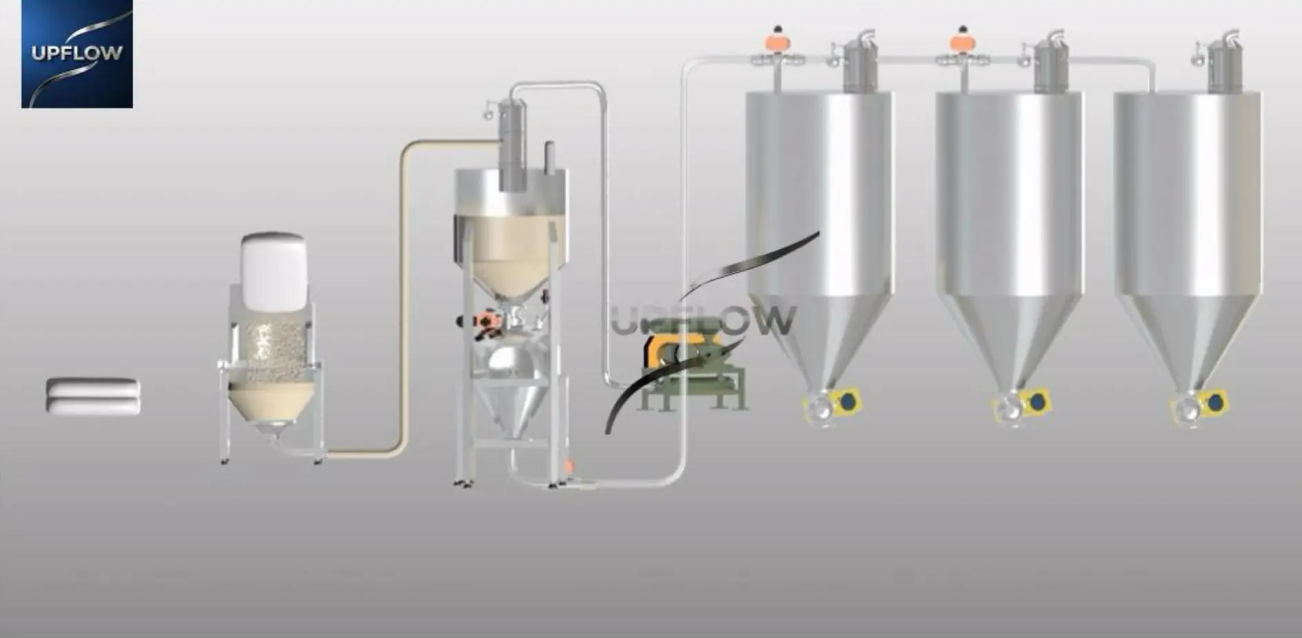
Image: the existing UPFLOW positive pressure pneumatic conveying system illustration, retained from this article.
Positive pressure pneumatic conveying pushes material through a line using gas supplied upstream; negative pressure pneumatic conveying draws material toward a receiver using a vacuum source downstream. Select between them by mapping the material sources, receiving points, route resistance, containment needs and production demand. Neither pressure direction alone guarantees a particular capacity, particle quality or operating cost.
For an early comparison, positive pressure is often a candidate for one source supplying one or several destinations, especially when the required route or throughput needs more pressure differential. Vacuum is often a candidate for collecting from several pickup points into receiving equipment. These are starting layouts, not exclusive rules: engineered vacuum networks can also serve multiple receivers.
How the two conveying systems work
Positive pressure conveying
A blower or compressor supplies conveying gas ahead of the material transport section. The feeding arrangement introduces solids into a line operating above atmospheric pressure. At the destination, equipment separates solids from conveying gas and vents or treats the gas as required. Feeding, pressure sealing and receiver venting must work together.
A rotary valve, pressure vessel or another suitable feeding arrangement may be used depending on the material and conveying mode. Review our positive pressure conveying system when evaluating this configuration.
Negative pressure or vacuum conveying
The vacuum source draws gas through the conveying route toward a receiving separator. Many batch vacuum receivers alternate between suction and discharge; other arrangements support different operating sequences. Material pickup, receiver filtration and discharge isolation determine how the system connects to the process.
Leaks in a section operating under vacuum tend to draw surrounding air inward. That can help limit outward powder leakage there, but may introduce moisture or contaminants and reduce useful conveying airflow. The vacuum feeding system must therefore be assessed together with its loading and discharge interfaces.
Source and destination selection matrix
Use this matrix to shortlist arrangements for engineering review. It is not a sizing chart or a guarantee of suitability for a particular powder.
| Plant requirement | Positive pressure candidate | Vacuum candidate | Confirm before selection |
|---|---|---|---|
| One source to one receiver | Often practical with suitable feed isolation | Often practical with a receiving separator | Pressure loss, material behavior and discharge interface |
| One source to multiple receivers | Common distribution arrangement using selected routes | Possible with coordinated receivers and vacuum resources | Simultaneous demand, routing valves and destination vents |
| Multiple sources to one receiver | Possible with engineered feed and routing arrangements | Common collection arrangement | Source selection, cross-contamination and line cleanout |
| Multiple sources to multiple receivers | Requires a defined routing and control plan | Requires a defined routing and control plan | Shared-resource schedule, product identification and peak demand |
| Long or demanding route | May offer a useful pressure-differential option | Check available vacuum and total resistance carefully | Calculated operating envelope, bends, lift and material trials where needed |
For an independent technical reference, Coperion’s ingredient transfer guidance describes both pressure and vacuum systems and both dilute and dense phase options. The pressure direction and the conveying phase answer different design questions.
Five conditions that can change the initial choice
1. Material quality and flow behavior
Provide bulk density, particle-size distribution, flowability, moisture sensitivity, abrasiveness and friability. Vacuum is not automatically gentle, and pressure is not automatically damaging. Gas velocity, solids loading, bends, pickup conditions and discharge impact all affect breakage and segregation. Agree how product quality will be evaluated after transfer.
2. Dust containment and product protection
Vacuum can reduce outward leakage from the suction line, while a pressure-line leak can release gas and powder outward. Neither arrangement is inherently dust-free across the entire installation: bag opening, receiver exhaust and discharge require their own controls. For sensitive materials, assess air ingress, conveying-gas quality, cleanability and the required containment boundary. Hazard controls and any certification must be specified for the actual material and installation.
3. Distance, lift and available pressure differential
There is no universal distance cutoff that selects pressure over vacuum. Total resistance depends on pipeline size and routing, solids rate, gas flow and material behavior. Ask for the design basis for your longest or most demanding route. A short route with difficult pickup or poor discharge can still be the limiting duty.
4. Batch delivery versus continuous process demand
Specify average throughput and peak refill demand separately. A batch receiver stops loading while it discharges or waits for process permission, so the suction rate alone cannot establish hourly delivery. Use our full-cycle vacuum conveying capacity worksheet to check timing, overlap and buffer requirements.
5. Utilities, maintenance and total operating cost
Compare proposed packages at the same delivered material rate and route, including filters, feed equipment, valves, controls and destination handling. State the utility measurement boundary and actual supply conditions. Neither vacuum nor pressure is always cheaper or more efficient; access for filter service, wear parts, cleaning and changeovers can change the lifecycle result.
Project reference: vacuum conveying to several PVC receiving points
The UPFLOW PVC powder feeding and vacuum conveying project includes bag unloading, multiple receiving points, pipeline engineering, receiving-hopper modifications, level detection and coordinated electrical control. It shows why the simple rule “vacuum means one destination” is too restrictive.
The project is a documented integration example, not proof that every PVC grade or plant layout should use the same equipment. Your material properties, required delivery and existing interfaces still need review.
What to send for a pressure-versus-vacuum recommendation
- A source-to-destination sketch showing distances, vertical lifts, bends and the receiving equipment.
- Material grade and handling data, including contamination, moisture and product-quality limits.
- Normal and peak demand, batch mass, refill deadlines and whether destinations run simultaneously.
- Available utilities, receiving-vessel pressure or venting conditions, and cleaning/changeover needs.
- Acceptance criteria for delivered throughput, product quality and containment.
Use the pneumatic conveying RFQ datasheet to assemble these inputs. For broader industry examples, see applications of pneumatic conveying systems.
Frequently asked questions
Is negative pressure conveying the same as dense phase conveying?
No. Negative pressure describes vacuum operation. Dense or dilute phase describes the gas–solids transport regime. Specify the pressure arrangement and conveying phase separately rather than treating the terms as interchangeable.
Can vacuum conveying supply more than one destination?
Yes, with an appropriate receiver, valve and control arrangement. Evaluate the demand schedule and shared vacuum resources rather than assuming that every receiving point can receive its maximum flow simultaneously.
Which type should be used for a clean production area?
Start with the containment and product-protection requirements. Vacuum may help control leakage along the suction route, but filters, connections, loading, discharge and cleanability still determine whether the complete installation meets the process requirements.
Can pressure and vacuum systems be combined?
Yes. Different sections of a process may use different pressure arrangements. Define the transfer interfaces, buffer capacity, isolation and control sequence so that one section does not disrupt another.
Discuss your conveying layout with UPFLOW
Explore the UPFLOW pneumatic conveying system range and send your material and route details for an application-specific review of pressure and vacuum options.